System and method for storing energy

a technology of energy storage and energy storage, applied in the field of system and method for storing energy, can solve the problems of environmental unfriendly, high cost of carrying extra disposable devices, and inherently limited the amount of portable stored energy available to users

Inactive Publication Date: 2010-03-30
BATTELLE ENERGY ALLIANCE LLC
View PDF135 Cites 114 Cited by
  • Summary
  • Abstract
  • Description
  • Claims
  • Application Information

AI Technical Summary

Benefits of technology

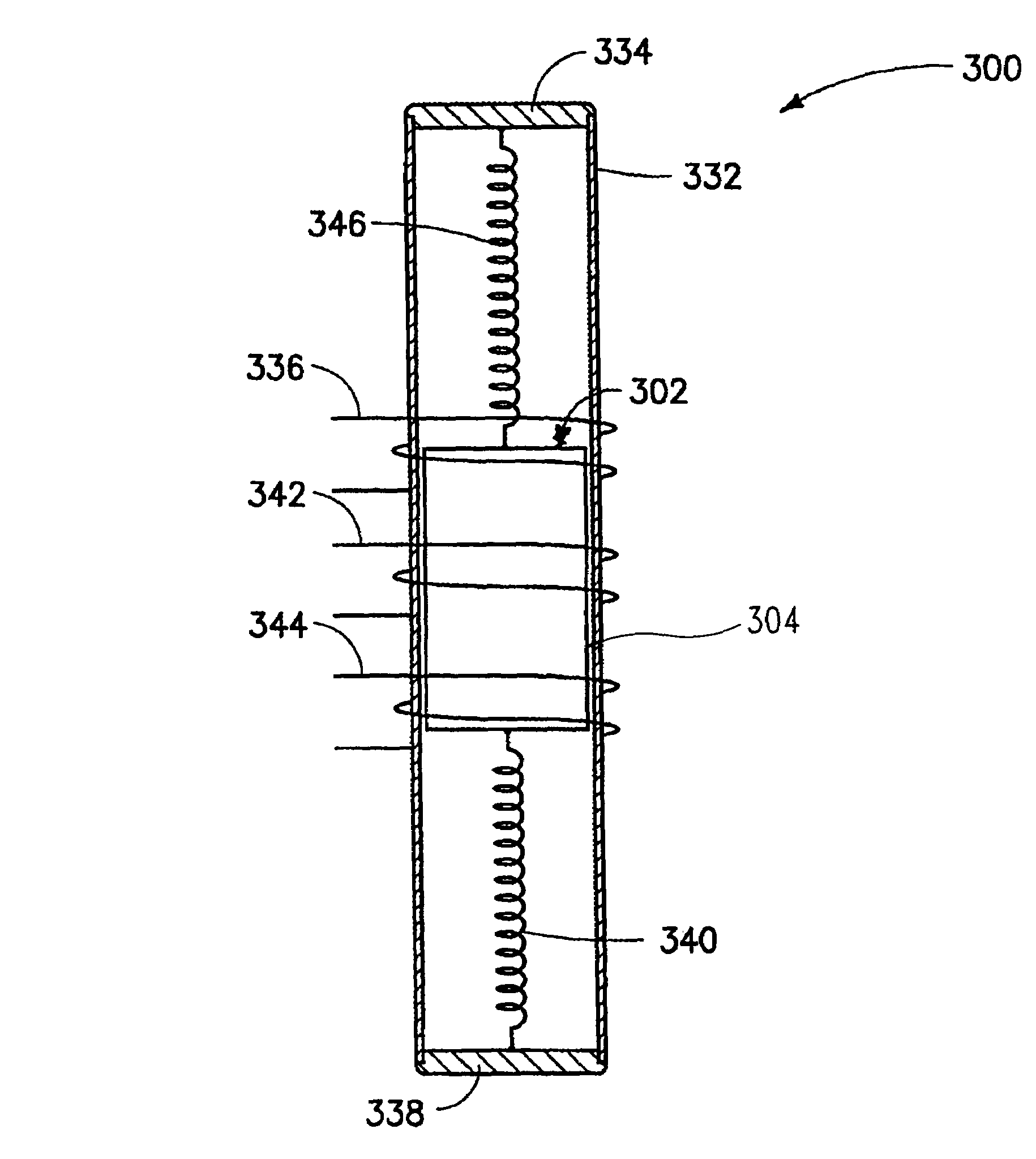
[0030]In one embodiment, a battery comprises a case, means for converting movement of the battery into an electric current, first means for storing energy contained within the case, second means for storing energy contained within the case, means for controlling a transfer of energy from the means for converting movement to the first means for storing energy contained within the case, and means for accessing energy stored in the first means for storing energy. In one embodiment, the battery further comprises third means for storing energy contained within the case. In one embodiment, the means for converting movement comprises means for conducting an electric current and means for generating a magnetic field. In one embodiment, the means for generating a magnetic field is configured to generate a compressed magnetic field. In one embodiment, the battery further comprises means for conducting magnetic flux. In one embodiment, the battery further comprises means for facilitating relative movement of the means for conducting an electric current with respect to the means for generating a magnetic field.

Problems solved by technology

Disposable devices inherently limit the amount of portable stored energy available to a user.
Carrying extra disposable devices is expensive, and a user must accommodate associated weight, storage space, and disposal requirements.
They also are environmentally unfriendly.
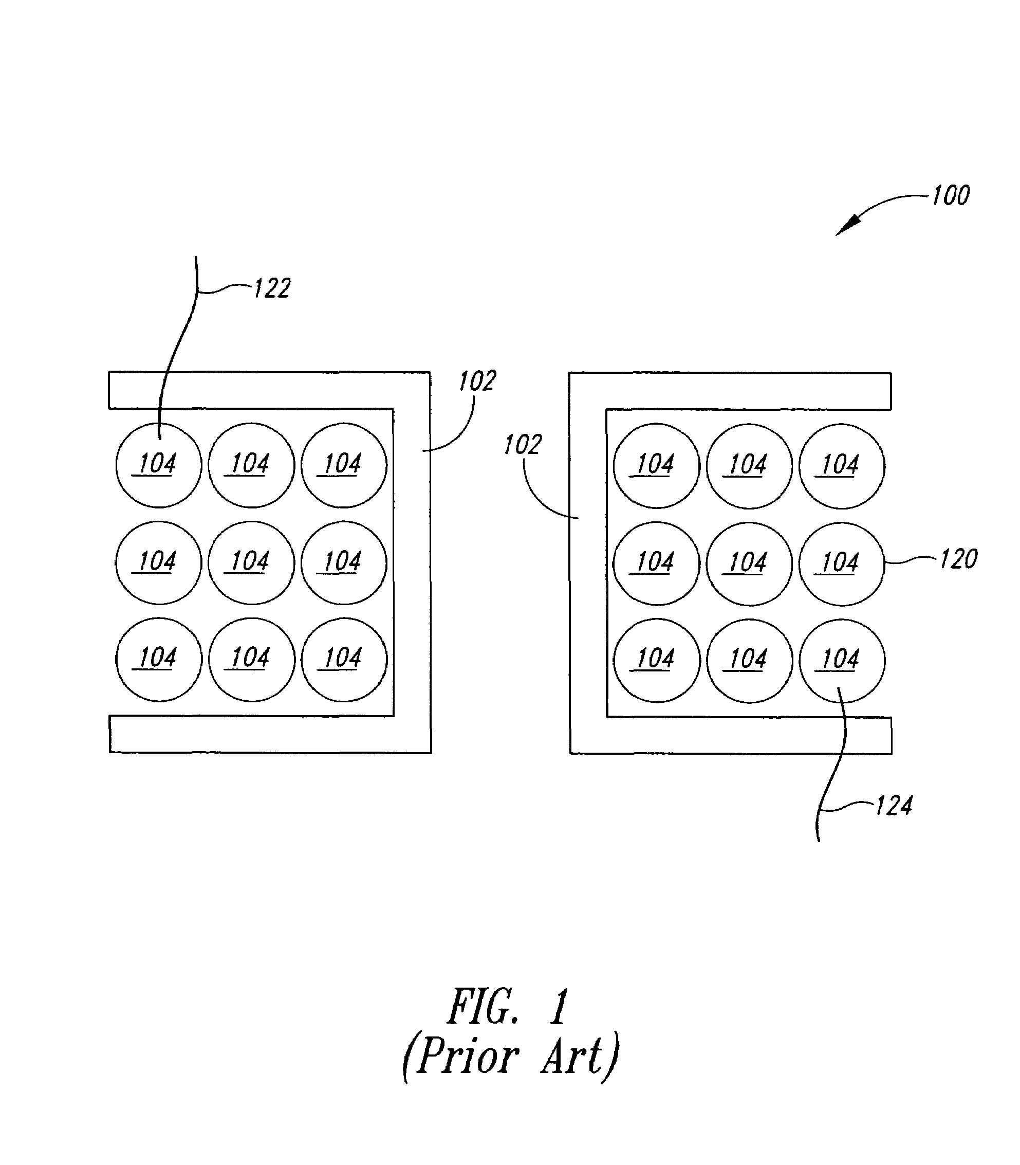
Conventional rechargeable devices are more environmentally friendly than non-rechargeable devices, but a remote source of energy is required to recharge the devices and the energy available between accesses to the remote source of energy is limited.
In addition, recharging requires user intervention.
Conventional shake-flashlights and similar shake-activated devices provide for storing limited amounts of energy, enough to power, for example, an LED for a brief period of time, but typically do not produce enough energy to power a conventional flashlight light bulb, and other high current draw devices, for example, a cell-phone, a camera, a GPS system or a conventional flashlight.
They also are bulky and require physical activity expressly directed to charging the device.
In addition, conventional shake-activated devices are not readily deployable to power another portable device.
They also produce objectionable levels of magnetic fields that can potentially interfere with the operation of electronic devices, such as cell-phones and health-related devices, such as pacemakers.
Conventional crank-powered devices have much more energy-storage capabilities than conventional shake-activated devices, but similarly are bulky, require physical activity expressly directed to recharging the device, are not readily deployable to power another portable device, and may generate objectionable levels of magnetic fields.
These approaches introduce weight, cost, size and durability issues.
These approaches also are not practical for many applications.

Method used


Image

  • System and method for storing energy
  • System and method for storing energy
  • System and method for storing energy

Examples


Embodiment Construction

[0081]In the following description, certain details are set forth in order to provide a thorough understanding of various embodiments of devices, methods and articles. However, one of skill in the art will understand that other embodiments may be practiced without these details. In other instances, well-known structures and methods associated with batteries, linear generators, and control systems have not been shown or described in detail to avoid unnecessarily obscuring descriptions of the embodiments.

[0082]Unless the context requires otherwise, throughout the specification and claims which follow, the word “comprise” and variations thereof, such as “comprising,” and “comprises,” are to be construed in an open, inclusive sense, that is as “including, but not limited to.”

[0083]Reference throughout this specification to “one embodiment,” or “an embodiment” means that a particular feature, structure or characteristic described in connection with the embodiment is included in at least ...


PUM

PropertyMeasurementUnit
voltagesaaaaaaaaaa
magneticaaaaaaaaaa
magnetic fieldaaaaaaaaaa

Abstract

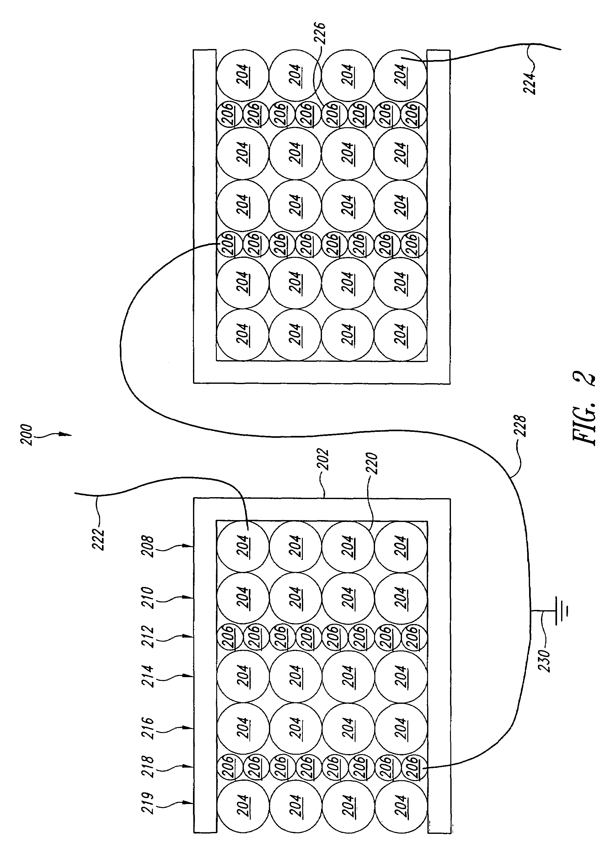
A self-recharging battery comprising a generator and an energy storage device contained within the battery case. The generator comprises a magnetic structure configured to generate a compressed magnetic field and a coil configured to focus the compressed magnetic field in electrical conductive elements of the coil.

Description

STATEMENT REGARDING GOVERNMENT INTEREST[0001]This invention was made with United States Government support under Contract No. DE-AC07-05-ID14517 awarded by the United States Department of Energy. The United States Government has certain rights in the invention.BACKGROUND OF THE INVENTION[0002]1. Field of the Invention[0003]This disclosure generally relates to a system and method for storing energy and more particularly to a system and method for portably converting energy into an electrical current and storing the energy.[0004]2. Description of the Related Art[0005]Conventional portable energy storage devices, such as conventional batteries and storage capacitors, are either disposable or rechargeable by coupling the device to a remote source of electrical energy. Disposable devices inherently limit the amount of portable stored energy available to a user. Carrying extra disposable devices is expensive, and a user must accommodate associated weight, storage space, and disposal requi...

Claims


Application Information

Patent Timeline
Patent Type & Authority Patents(United States)
IPC IPC(8): H02J7/00G11B13/00H04B1/38H01F27/02
CPCH01M6/5033H02K35/02H01M10/44H02J7/32H02J7/345H01M10/4264H01M6/42H01M10/052Y02E60/10
Inventor YARGER, ERIC JAYMORRISON, JOHNRICHARDSON, JOHN GRANTSPENCER, DAVID FRAZERCHRISTIANSEN, DALE W.
Owner BATTELLE ENERGY ALLIANCE LLC
Why Eureka
Try Eureka