Polar modulation transmission circuit and communication device
a transmission circuit and polar modulation technology, applied in the field of transmission circuits, can solve the problems of low power efficiency, enlarging the device, and radio frequency power amplifiers having a problem of being usable for only a short period of time, so as to prevent the characteristic of the amplitude modulation section from deteriorating, increase the output power, and reduce the distortion
- Summary
- Abstract
- Description
- Claims
- Application Information
AI Technical Summary
Benefits of technology
Problems solved by technology
Method used
Image
Examples
first embodiment
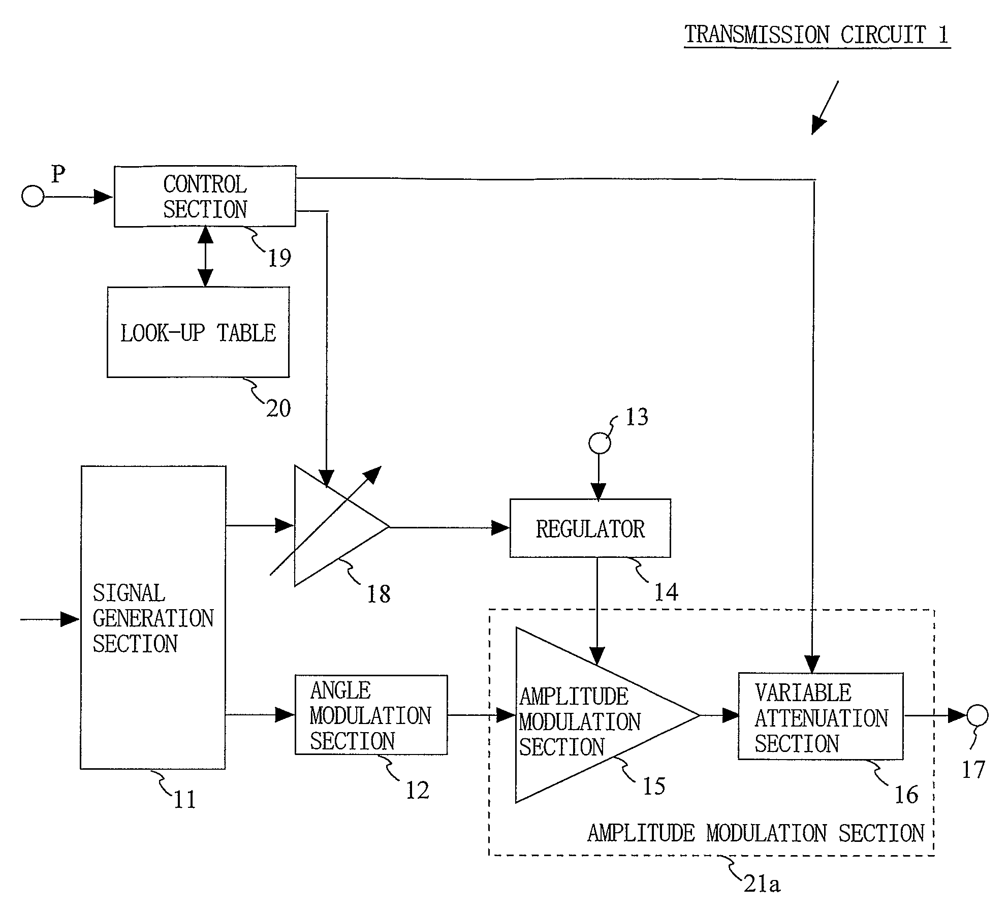
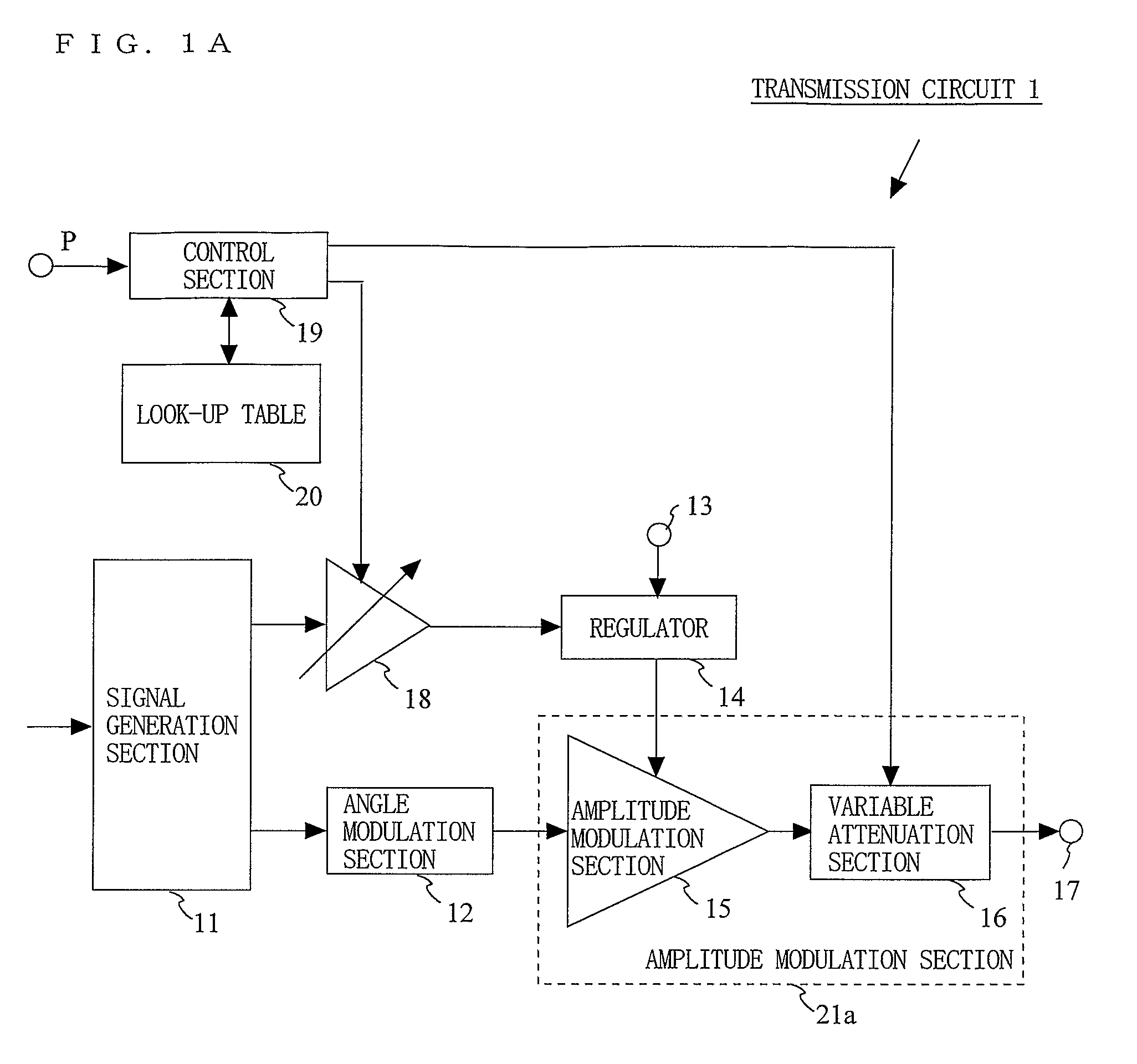
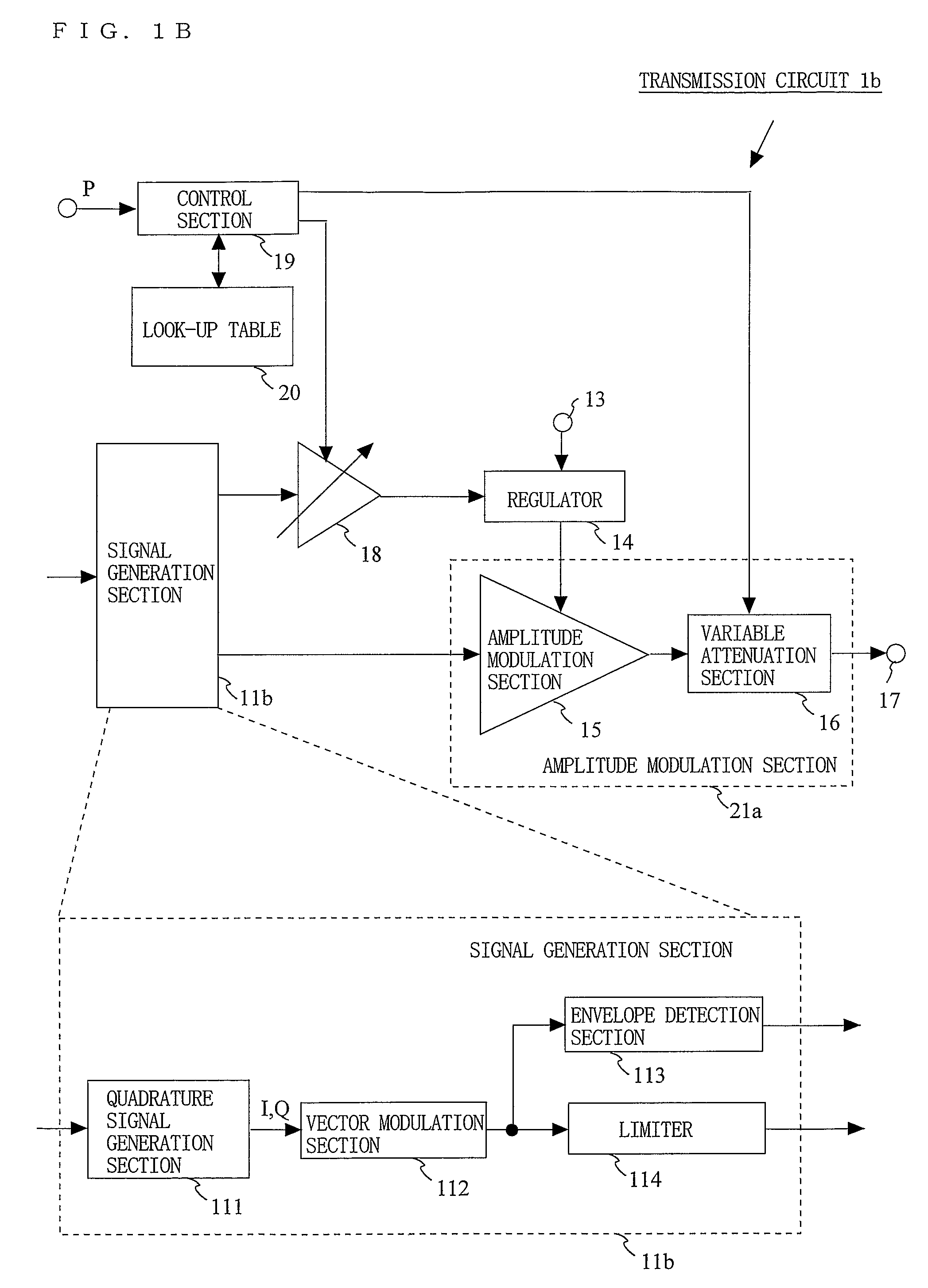
[0064]FIG. 1A is a block diagram showing an exemplary structure of a transmission circuit 1 according to a first embodiment of the present invention. As shown in FIG. 1A, the transmission circuit 1 includes a signal generation section 11, an angle modulation section 12, a power source terminal 13, a regulator 14, an amplitude modulation section 15, a variable attenuation section 16, an output terminal 17, a variable gain amplification section 18, a control section 19, and a look-up table 20.
[0065]The signal generation section 11 outputs an amplitude signal and a phase signal based on an amplitude component and a phase component obtained by performing signal processing on input data. The signal generation section 11 can include, for example, a polar coordinate signal generation section (not shown) for generating a polar coordinate signal. The polar coordinate signal generation section modulates input data and generates an amplitude signal and a phase signal, which are polar coordinat...
second embodiment
[0089]FIG. 9 is a block diagram showing an exemplary structure of a transmission circuit 2 according to a second embodiment of the present invention. As shown in FIG. 9, the transmission circuit 2 includes a signal generation section 11, an angle modulation section 12, a power source terminal 13, a regulator 14, an amplitude modulation section 15, a variable attenuation section 26, an output terminal 17, a variable gain amplification section 28, and a control section 29. In the transmission circuit 2 according to the second embodiment, the variable attenuation section 26, the variable gain amplification section 28 and the control section 29 operate in a different manner from those of the transmission circuit 1 according to the first embodiment.
[0090]In the transmission circuit 2, an assembly of the amplitude modulation section 15 and the variable attenuation section 26 may be labeled simply as an amplitude modulation section 21b, like in the transmission circuit 1.
[0091]FIG. 10 is a...
third embodiment
[0099]FIG. 12 is a block diagram showing an exemplary structure of a transmission circuit 3 according to a third embodiment of the present invention. Referring to FIG. 12, in the transmission circuit 3, a variable attenuation section 26b, a variable gain amplification section 28b, and a control section 29b operate in a different manner from those in the transmission circuit 2 according to the second embodiment. In the third embodiment, the variable attenuation section 26b can switch the attenuation by values greater than binary values. The variable gain amplification section 28b can switch the gain by values greater than binary values.
[0100]In the transmission circuit 3, an assembly of the amplitude modulation section 15 and the variable attenuation section 26b may be labeled simply as an amplitude modulation section 21c, like in the transmission circuit 1.
[0101]FIG. 13 is a block diagram showing an exemplary structure of the variable attenuation section 26b capable of switching the...
PUM
 Abstract
Description
Claims
Application Information
 - R&D
- Intellectual Property
- Life Sciences
- Materials
- Tech Scout
- Unparalleled Data Quality
- Higher Quality Content
- 60% Fewer Hallucinations
Browse by: Latest US Patents, China's latest patents, Technical Efficacy Thesaurus, Application Domain, Technology Topic, Popular Technical Reports.
© 2025 PatSnap. All rights reserved.Legal|Privacy policy|Modern Slavery Act Transparency Statement|Sitemap|About US| Contact US: help@patsnap.com


