
Monitoring control system and method

a technology of monitoring control system and mobile communication device, which is applied in the direction of transmission monitoring, receiver monitoring, instruments, etc., can solve the problems of inability to monitor mobile terminals in real time, unstable mobile terminals, and network delay in conventional monitoring control systems, so as to achieve the effect of reducing network delay

Inactive Publication Date: 2010-03-30
LG ELECTRONICS INC
View PDF11 Cites 99 Cited by
  • Summary
  • Abstract
  • Description
  • Claims
  • Application Information

AI Technical Summary

Benefits of technology

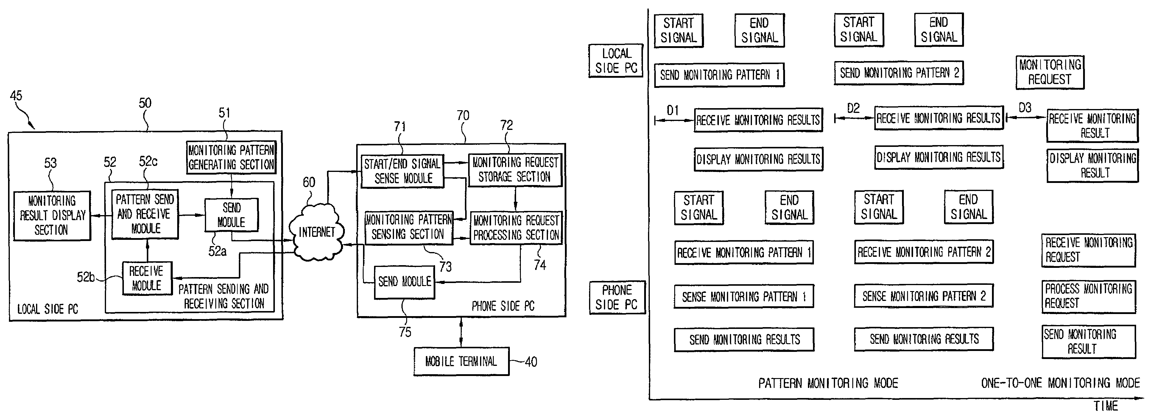
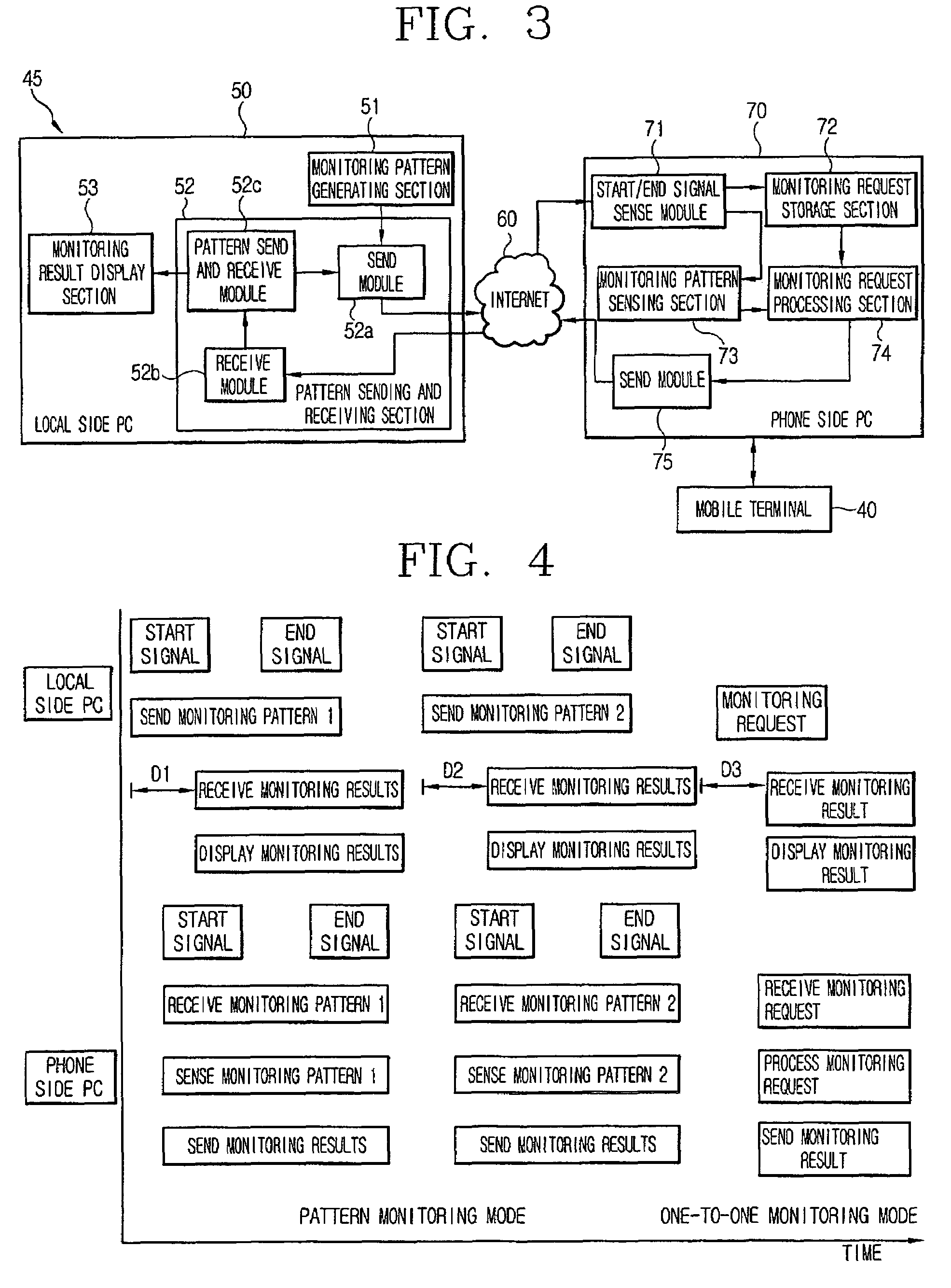
The invention is a monitoring control system for a mobile communication device that can minimize network delay when monitoring a mobile communication device in real-time. The system includes a controller that sends and receives monitoring requests and results through the internet. The monitoring unit includes a signal sense module that senses the start and end signals, a monitoring request storage section that stores the monitoring requests, a monitoring pattern sensing section that senses each monitoring request and generates a monitoring sense signal, and a monitoring result display section that sequentially displays or collates and sorts the monitoring results. The system can be used to monitor various applications of the mobile communication device.

Problems solved by technology

Furthermore, as the operation of a mobile terminal has become more complicated, the interaction between various operations of a mobile terminal sometimes is not smooth, thereby making the mobile terminal unstable.
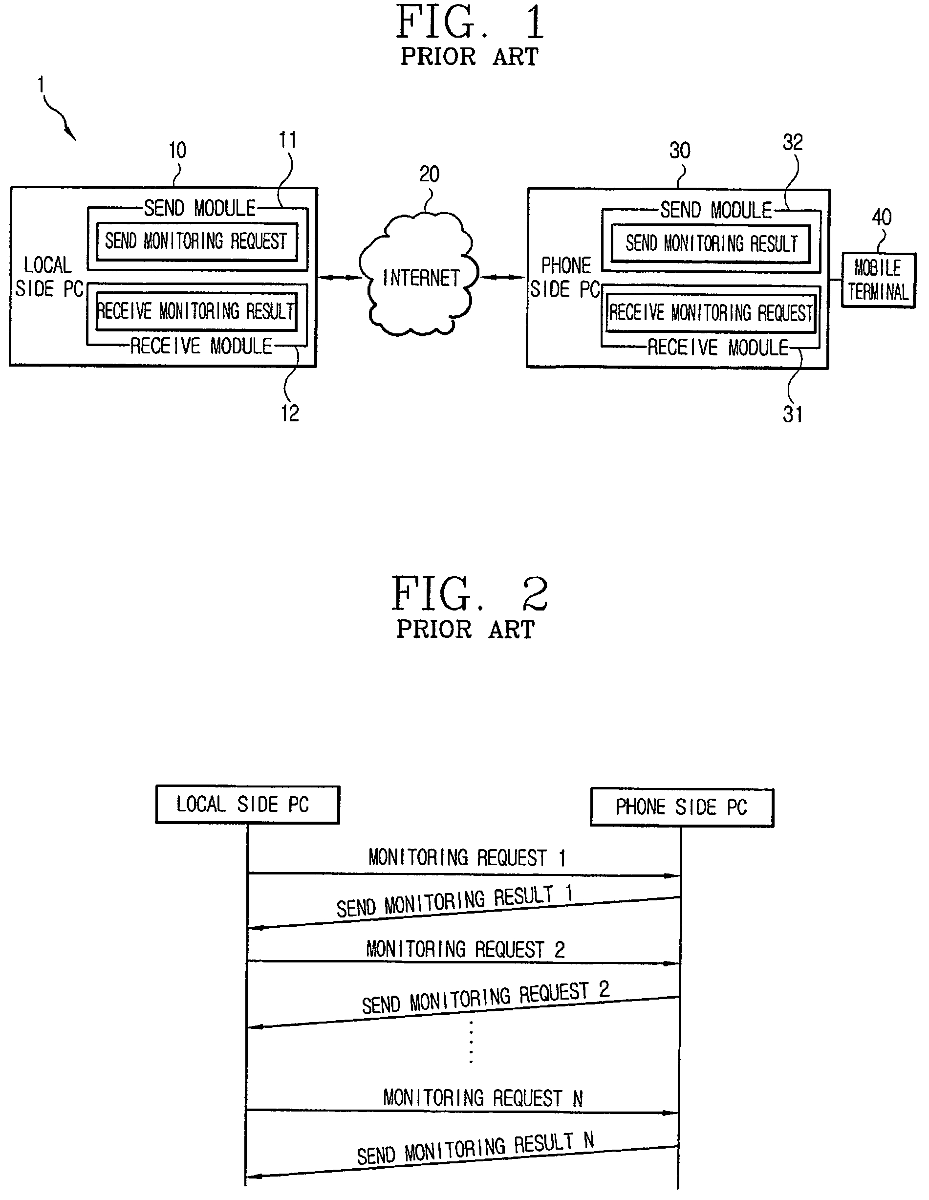
Consequently, a network delay occurs in the conventional monitoring control system because the local side PC 10 waits until a monitoring result is received before sending another monitoring request.
Furthermore, the conventional monitoring control system has a disadvantage in that, if a network delay occurs due to the transit via the Internet when sending and receiving the monitoring request and the monitoring result, the mobile terminal cannot be monitored in real time.
Moreover, the conventional monitoring control system has a disadvantage in that the local side PC and the phone side PC are disconnected if the network delay becomes too long.

Method used


Image

  • Monitoring control system and method
  • Monitoring control system and method
  • Monitoring control system and method

Examples


Embodiment Construction

[0036]The present invention is directed to a monitoring control system and method that can minimize network delay between a local side PC and a phone side PC when monitoring a mobile communication device in real time. Although the present invention is illustrated with respect to monitoring a mobile terminal using PCs, it is contemplated that the present invention may be utilized anytime it is desired to monitor a mobile communication device in real time with minimized network delay between a first monitoring device and a second monitoring device.

[0037]As used herein, a PC having a controller adapted to consecutively send a plurality of monitoring requests for monitoring a mobile terminal via the Internet is referred to as a local side PC. As used herein, a PC having a monitoring unit that is connected to the mobile terminal and is adapted to receive a plurality of monitoring requests via the internet, monitor a plurality of applications according to the plurality of monitoring reque...


PUM


Abstract

Disclosed is a monitoring control system and method that can minimize network delay between a local side PC and a phone side PC when monitoring a mobile communication device in real time. By consecutively sending a plurality of monitoring requests for monitoring the mobile communication device via the Internet, monitoring the mobile communication device and consecutively receiving a plurality of monitoring results corresponding to the plurality of monitoring requests via the Internet, real time monitoring of the mobile communication device is facilitated with minimized delay.

Description

CROSS-REFERENCE TO RELATED APPLICATIONS[0001]Pursuant to 35 U.S.C. §119(a), this application claims the benefit of earlier filing date and right of priority to Korean Application No. 95933 / 2004, filed on Nov. 22, 2004, the contents of which is hereby incorporated by reference herein in its entiretyBACKGROUND OF THE INVENTION[0002]1. Field of the Invention[0003]The present invention relates to a monitoring unit for a mobile communication device, and more particularly, to a monitoring control system and method for a mobile communication device.[0004]2. Description of the Related Art[0005]As the types of mobile terminals and the services offered by mobile terminals have varied, the size of program code required to support a plurality of services has increased. Furthermore, as the operation of a mobile terminal has become more complicated, the interaction between various operations of a mobile terminal sometimes is not smooth, thereby making the mobile terminal unstable.[0006]In order t...

Claims


Application Information

Patent Timeline
Patent Type & Authority Patents(United States)
IPC IPC(8): H04L12/50G06F11/22G06F13/00H04B17/00H04B17/18H04B17/29H04W24/00H04W24/06H04W24/10H04W88/02
CPCH04L67/025H04L67/125H04L67/04H04L67/02G06F15/16G06F11/28
Inventor SHIN, SANG-CHEOLKIM, KYUNG-HOONJUNG, JONG-CHEOLJUNG, YOUNG-HO
Owner LG ELECTRONICS INC
Learn More