Double-walled chamber for ultraviolet radiation treatment of liquids

a technology of ultraviolet radiation treatment and double-walled chamber, which is applied in the direction of chemical/physical/physical-chemical processes, chemical apparatus and processes, energy-based chemical/physical/physical-chemical processes, etc., can solve the problems of unsatisfactory classical ideal and laminar flow pattern, and the inability to conveniently arrange uv radiation sources or lamps along the chamber in a circular fashion,

Inactive Publication Date: 2010-04-06
TROJAN TECH
View PDF9 Cites 9 Cited by
  • Summary
  • Abstract
  • Description
  • Claims
  • Application Information

AI Technical Summary

Benefits of technology

[0011]It is an object of the present invention to provide a novel chamber, vessel or treatment device of obviates or mitigates at least one of the above-mentioned disadvantages of the prior art.

Problems solved by technology

The classical ideal and laminar flow pattern is therefore not desirable.
The occurrence of dead zones by the lateral entrance of the medium into the cylindrical radiation chamber which are caused by too fast and uncontrollable deflection of the incoming liquid stream and a lack of inner radial movement components often prevent the utilization of the theoretically available radiation space (radiation duration) in the cylindrical radiation chambers.
An additional factor is that the UV radiation sources or lamps disposed along the chamber cannot be conveniently arranged in a circular pattern such that one can refer to a homogeneous radiation field over the cross section and thus in the entire chamber volume.
Unfortunately, such an arrangement becomes problematic, however, when a considerable pressure prevails in the interior of the chambers, which is nearly always the case in the treatment of drinking water.

Method used


Image

  • Double-walled chamber for ultraviolet radiation treatment of liquids
  • Double-walled chamber for ultraviolet radiation treatment of liquids
  • Double-walled chamber for ultraviolet radiation treatment of liquids

Examples


Embodiment Construction

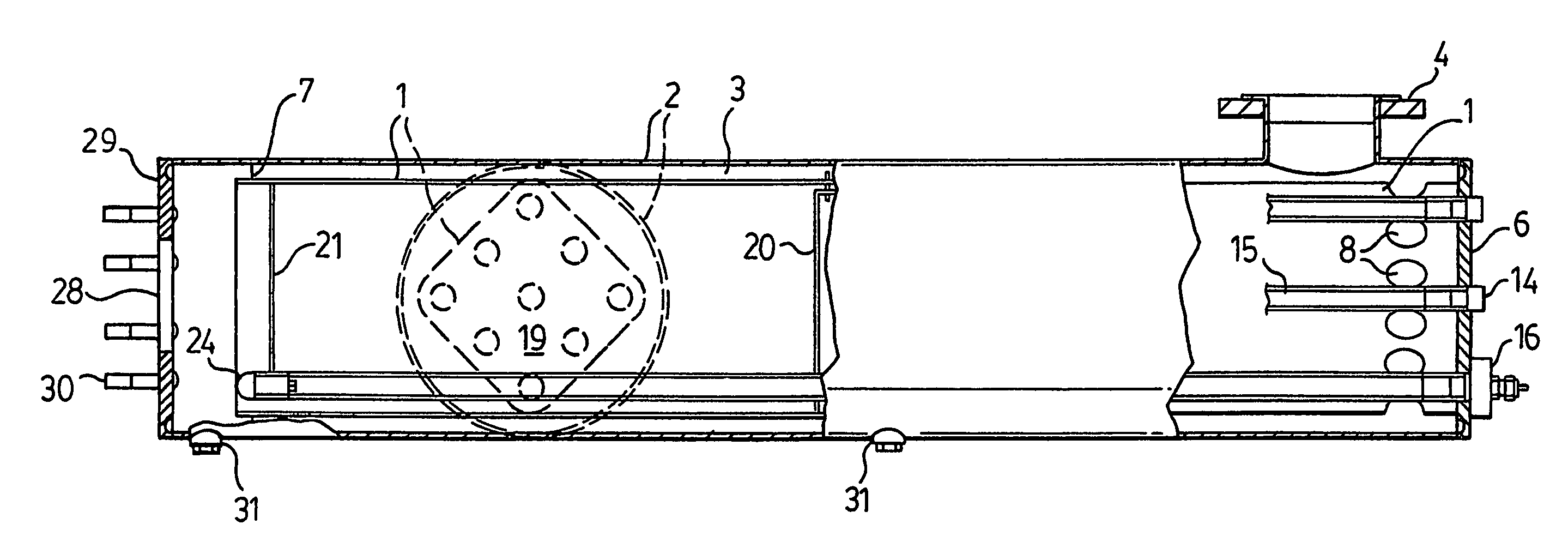
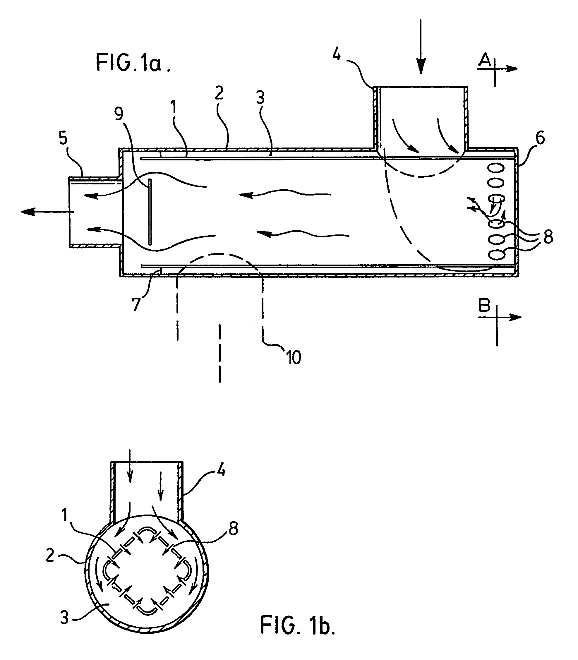
[0017]Thus, a preferred embodiment of the present invention is illustrated in FIGS. 1a and 1b, in which, for clarity, the UV radiation devices, i.e. the UV radiation sources or lamps with the cladding tubes and the radiation source or lamp hatches, are not shown. Instead, there is illustrated only the double chamber with the guidance of the passing medium.

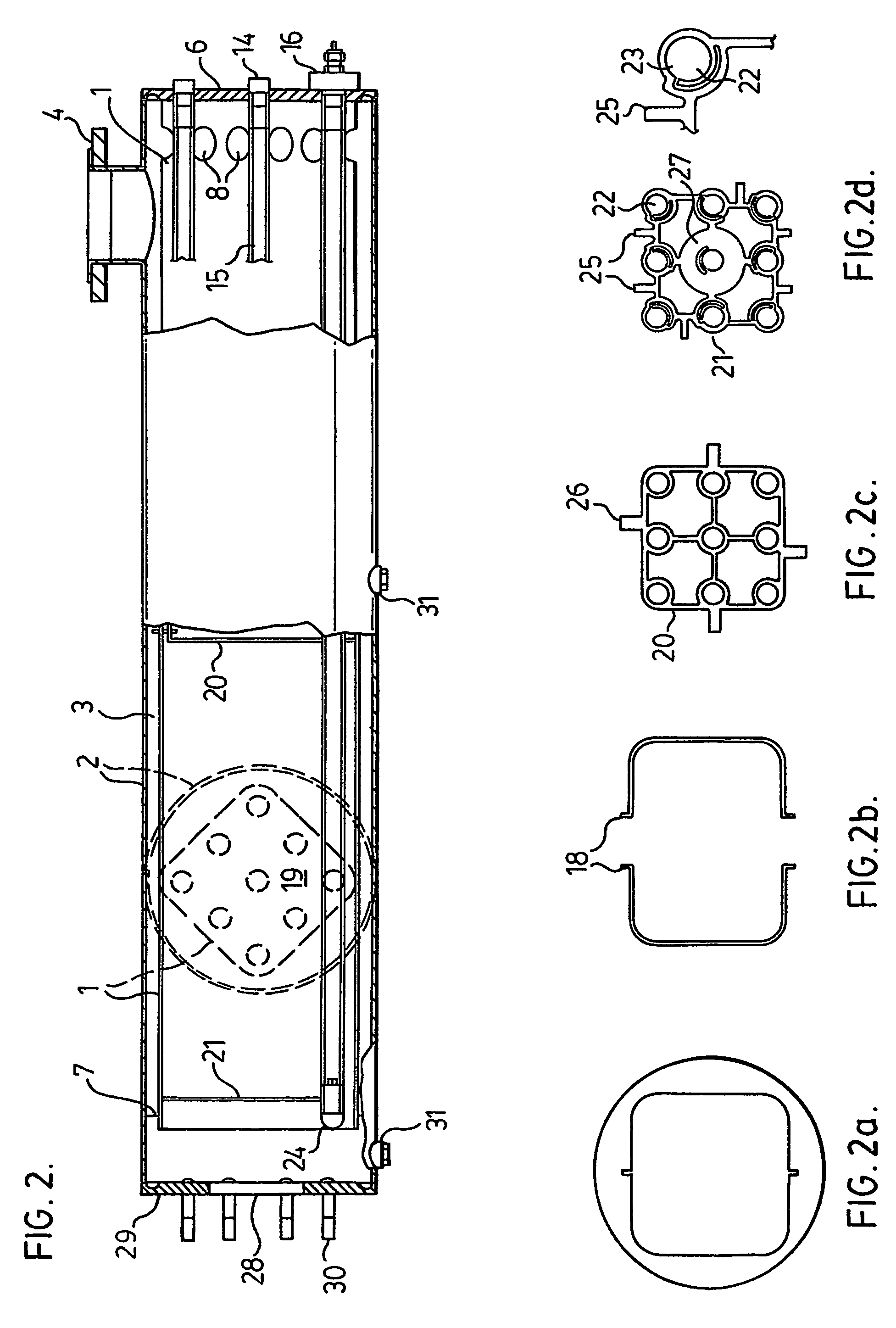
[0018]With reference to FIGS. 1a and 1b, reference numeral 1 relates to the thin-walled inner pipe of any random cross-section, e.g., a square cross section, in which the UV radiation source or lamp configuration is disposed. Reference numeral 2 relates an outer pressure-tight round pipe with an inlet nozzle 4 and an outlet nozzle 5. Reference numeral 3 relates to the intermediate space between the two pipes 1 and 2.

[0019]The inner pipe 1 is tightly connected with the round floor 6, e.g., by welding on the face surface at the outlet end of the chamber and centering by means of the adapted separating wall 7 at the end side. The inne...


PUM

PropertyMeasurementUnit
thicknessaaaaaaaaaa
thicknessaaaaaaaaaa
radiusaaaaaaaaaa

Abstract

The object of the invention is a double-walled chamber for the UV disinfection of liquids, preferably drinking water and / or waste water. It realizes a rectangular and / or square cross-sectional shape of the UV radiation chamber even at higher pressures, whereby the radiation chamber can moreover be provided with a thin-walled configuration and allows an optimal and close arrangement of UV radiators as compared with a round chamber. By applying the inventive idea, the known dead zones at the entrance are completely eliminated and an entrance turbulence is produced which runs simultaneously with the piston flow in the chamber.

Description

[0001]This application is a 371 of PCT / CA03 / 00656, filed May 9, 2003 (designating the U.S.; and which published in English in WO 03 / 095369 on Nov. 20, 2003), which claims the benefit of German Patent Application No. 102 21 037.3, May 10, 2002, incorporated herein by reference.FIELD OF THE INVENTION[0002]In one of its aspects, the present invention relates to a double-walled chamber, particularly such a chamber suitable use in the ultraviolet (UV) treatment or disinfection of liquids, preferably drinking water and / or wastewater.DESCRIPTION OF THE PRIOR ART[0003]UV radiation chambers are usually round boiler-like vessels through which the medium to be treated flows axially. Typically, a conventional UV radiation chamber is provided with inlet and outlet connections laterally at the end, partly also with axially directed outlets. It is conventional that the inlet and outlet connections, like other pressure vessels, are manufactured from round pipes, typically standardized special steel...

Claims


Application Information

Patent Timeline
Patent Type & Authority Patents(United States)
IPC IPC(8): B01J19/12A61L2/10C02F1/00C02F1/32
CPCA61L2/10B01J19/123C02F1/325B01J2219/0869C02F2301/02C02F2201/3227B01J2219/0877C02F1/32
Inventor UEBERALL, PETER
Owner TROJAN TECH
Why Eureka
Try Eureka