Method for fabricating magnetoresistive read head having a bias structure with at least one dusting layer

a read head and bias structure technology, applied in the field of magnetic storage, can solve problems such as non-uniformity of the bias field at the edges of the free layer

Inactive Publication Date: 2010-04-06
WESTERN DIGITAL TECH INC
View PDF11 Cites 149 Cited by
  • Summary
  • Abstract
  • Description
  • Claims
  • Application Information

AI Technical Summary

Problems solved by technology

For example, the granular nature of the HB layer can cause non-uniformity of the bias field at the edges of the free layer.

Method used


Image

  • Method for fabricating magnetoresistive read head having a bias structure with at least one dusting layer
  • Method for fabricating magnetoresistive read head having a bias structure with at least one dusting layer
  • Method for fabricating magnetoresistive read head having a bias structure with at least one dusting layer

Examples


Embodiment Construction

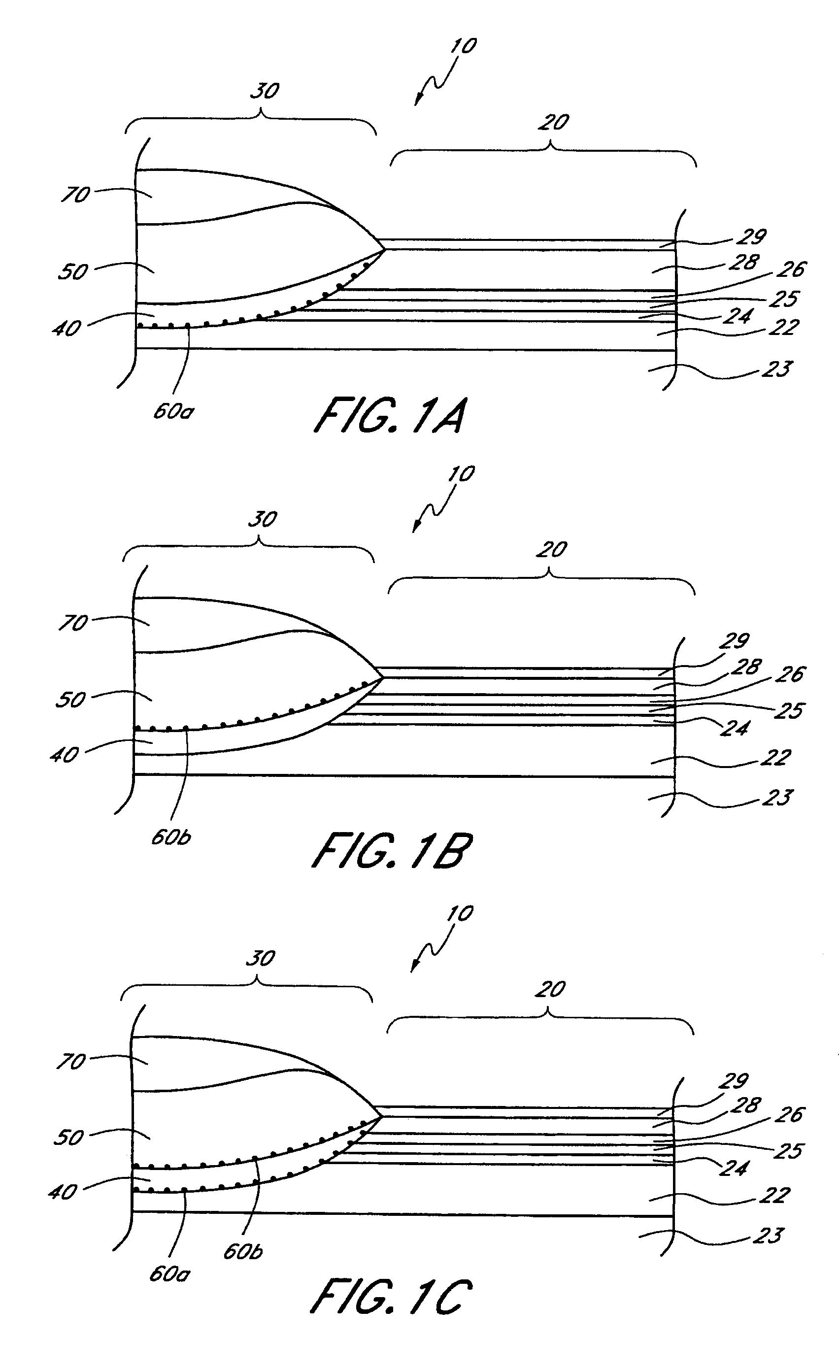
[0019]FIGS. 1A-1C schematically illustrate various embodiments of the present invention with an abutted junction structure. A magnetoresistive (“MR”) read head 10 comprises a MR sensor 20 and a bias structure 30 adjacent to the MR sensor 20. The bias structure 30 provides a magnetostatic bias field for the MR sensor 20. The bias structure 30 comprises an underlayer 40, a hard bias (“HB”) layer 50 over the underlayer 40, and at least one dusting layer 60a or 60b. The dusting layer 60a or 60b is directly below at least one of the underlayer 40 or the HB layer 50. In the embodiment schematically illustrated by FIG. 1A, the dusting layer 60a is directly below the underlayer 40. In the embodiment schematically illustrated by FIG. 1B, the dusting layer 60b is directly below the HB layer 50. In embodiments with two dusting layers, such as the embodiment schematically illustrated by FIG. 1C, a first dusting layer 60a is directly below the underlayer 40 and a second dusting layer 60b is dire...


PUM

PropertyMeasurementUnit
time periodaaaaaaaaaa
grain sizesaaaaaaaaaa

Abstract

A method of fabricating a bias structure of a magnetoresistive read head for a magnetoresistive sensor stack formed on a substrate includes forming an underlayer and forming a bias layer over the underlayer. The method further includes forming a dusting layer directly below at least one of the underlayer or the bias layer and between the bias layer and the magnetoresistive sensor stack. The dusting layer includes discontinuous, nano-sized islands.

Description

CROSS-REFERENCE TO RELATED APPLICATION[0001]This application is a divisional of U.S. patent application Ser. No. 10 / 769,239, filed Jan. 31, 2004 now U.S. Pat. No. 7,342,752, which is incorporated herein by reference in its entirety.BACKGROUND OF THE INVENTION[0002]1. Field of the Invention[0003]This invention relates generally to the field of magnetic storage, and more particularly to the field of magnetoresistive read heads.[0004]2. Description of the Related Art[0005]Magnetoresistive (“MR”) read heads for magnetic storage devices (e.g., disk drives) utilize MR sensors (e.g., giant magnetoresistive or “GMR” sensors) which comprise a ferromagnetic free layer having a magnetization orientation which can be switched between two states by applying a magnetic field. When reading data from magnetic media, magnetic fields from the data bits being read induce the magnetization orientation of the free layer to be in one of the two states. Since the resistance of the MR sensor depends on the...

Claims


Application Information

Patent Timeline
Patent Type & Authority Patents(United States)
IPC IPC(8): G11B5/39C23C14/46
CPCB82Y10/00B82Y25/00G11B5/3909G11B5/3932G11B2005/3996G11B5/3163
Inventor ZHANG, WEICHEN, YINGJIANARAKI, SATORUKROUNBI, MOHAMAD T.
Owner WESTERN DIGITAL TECH INC
Why Eureka
Try Eureka