
Coaxial cable having wide continuous usable bandwidth

a technology of continuous usable bandwidth and coaxial cable, which is applied in the direction of power cables, cables, insulated conductors, etc., can solve the problems of limited bending characteristics, adversely affecting the electrical properties of the cable, and/or rendering it unusable, and air dielectric type coaxial cables typically require very careful handling

Inactive Publication Date: 2010-04-06
COMMSCOPE INC +2
View PDF13 Cites 33 Cited by
  • Summary
  • Abstract
  • Description
  • Claims
  • Application Information

AI Technical Summary

Benefits of technology

The optimized coaxial cable achieves a velocity of propagation greater than 88%, improved bending characteristics, and ease of connectorization, enabling reliable high-frequency signal transmission and installation in various environments while maintaining structural integrity.

Problems solved by technology

However, these coaxial cables unfortunately have relatively limited bending characteristics and are typically susceptible to buckling, flattening or collapsing of the outer sheath, which may adversely affect the electrical properties of the cable and / or render it unusable.
Consequently, air dielectric type coaxial cables typically require very careful handling during installation to avoid such damage.
Additionally, they may not be recommended for use in installations requiring small radius bends or frequent reverse bends.
Extended frequencies beyond 1 GHz can cause the disk spacing to become much closer, thus increasing Vp attenuation, and cost.
However, they can be hampered by a somewhat lower velocity of propagation than air dielectric type cables.
In addition, foam dielectric cables typically present more difficulties with attachment of the cable to connectors and couplings.
In most instances the dielectric material is bonded to the core and sheath with an adhesive, which can further complicate the coring process.

Method used


Image

  • Coaxial cable having wide continuous usable bandwidth
  • Coaxial cable having wide continuous usable bandwidth
  • Coaxial cable having wide continuous usable bandwidth

Examples


example 1

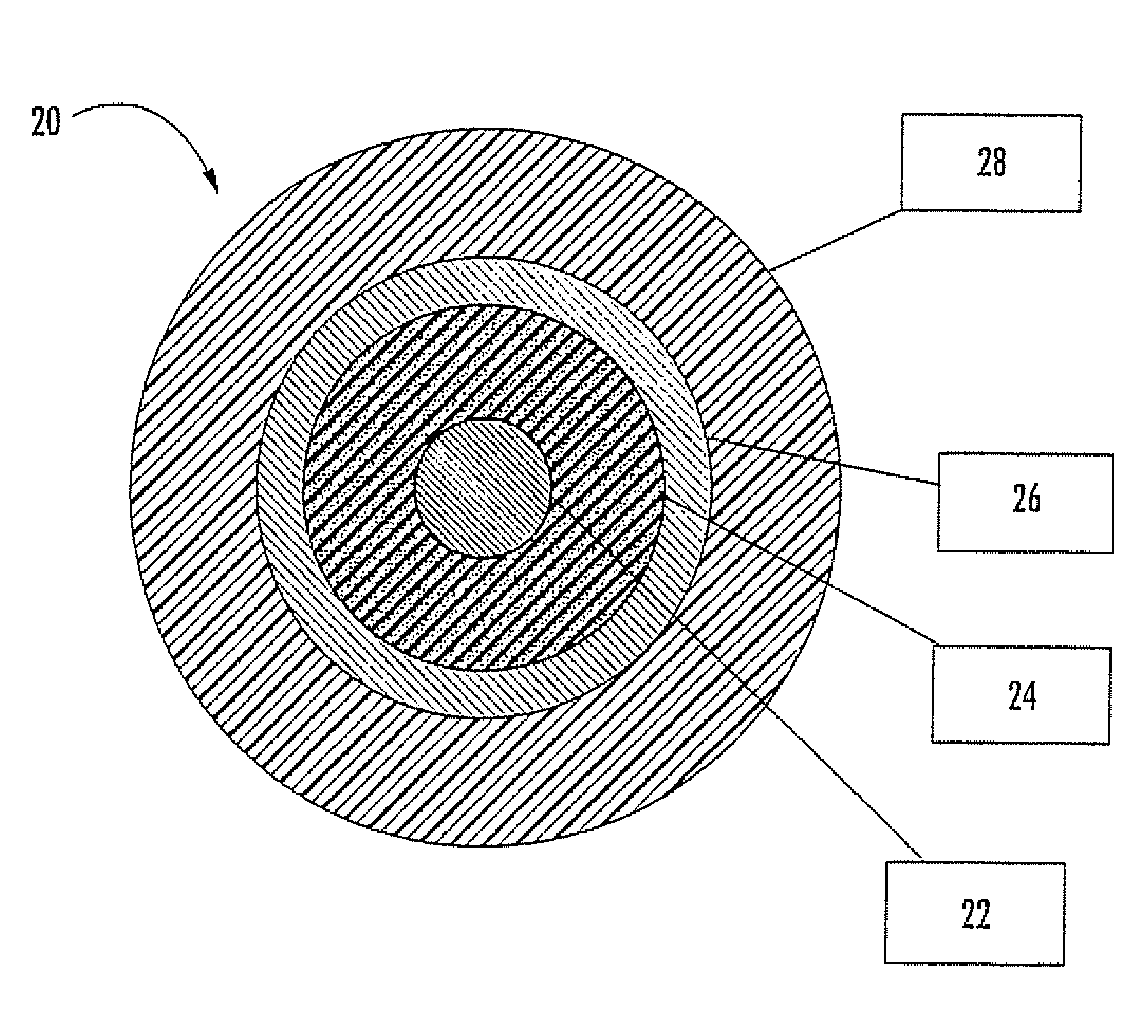
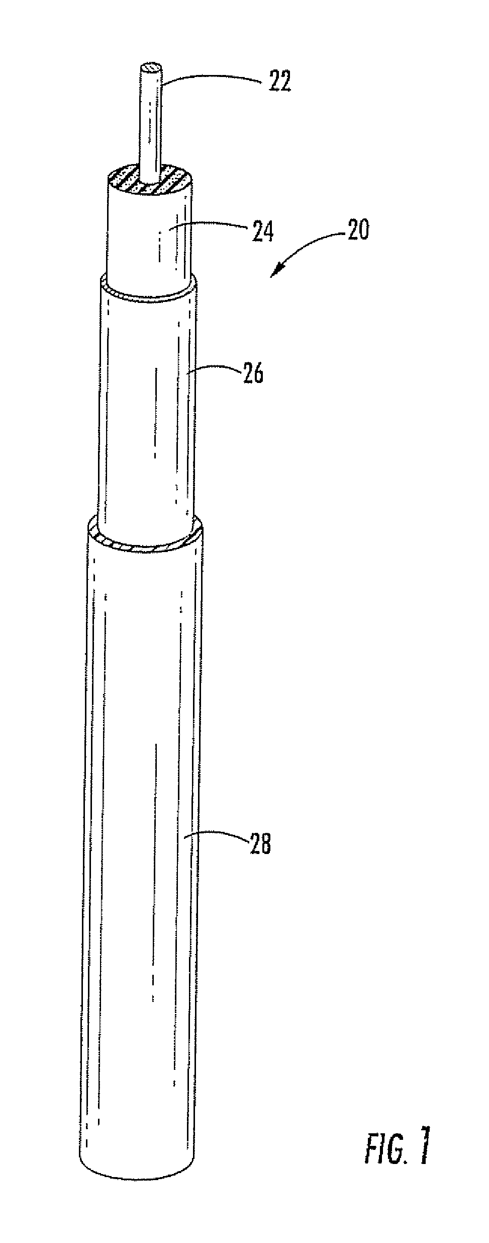
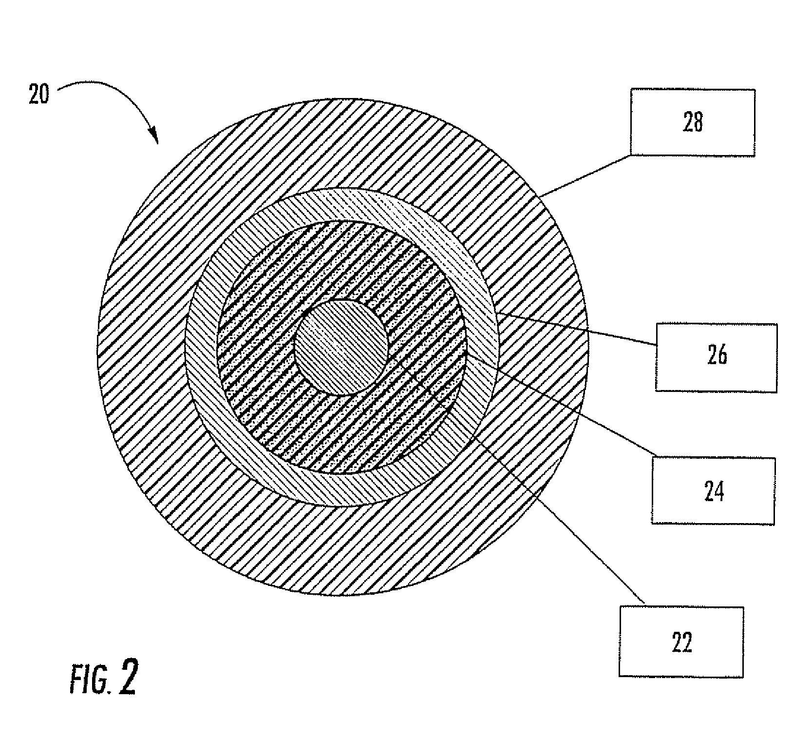
[0042]A cable can be constructed according to the parameters set forth in Table 1.

[0043]

TABLE 1ComponentMaterialSize (in.)ConductorCCA0.166 ODDielectric Layer85% HDPE / 15% LDPE0.686 ODdensity ≦ 0.215 g / ccAdhesiveAggressiveShieldAluminum0.715 ODJacketMDPE and carbon black0.785 OD

[0044]This cable has the following properties set forth in Table 2.

[0045]

TABLE 2PropertyValueNominal Impedance75 Ω± 2 ΩAttenuation1.52 db / 100 ft @ 1 GHzReverse Bending69 cycles to failureMinimum Bend Radius5 in.Cyclic Expansion Loop Fatigue23,500 cyclesVelocity of Propagation89 percent

example 2

[0046]A cable can be constructed according to the parameters set forth in Table 3.

[0047]

TABLE 3ComponentMaterialSize (in.)ConductorCCA0.166 ODInsulator85% HDPE / 15% LDPE0.686 ODdensity ≦ 0.215 g / ccAdhesiveControlledShieldAluminum0.715 ODJacketMDPE and carbon black0.785 OD

[0048]This cable has the following properties set forth in Table 4.

[0049]

TABLE 4PropertyValueNominal Impedance75 Ω± 2 ΩReverse Bending69 cyclesMinimum Bend RadiusApproximately 3 in.Cyclic expansion Loop Fatigue23,500 cyclesCoringCored cleanlyVelocity of Propagation89 percent

example 3

[0050]A cable can be constructed according to the parameters set forth in Table 5.

[0051]

TABLE 5ComponentMaterialSize (in.)ConductorCCA0.166 ODInsulator85% HDPE / 15% LDPE0.686 ODdensity ≦ 0.215 g / ccAdhesiveControlledShieldAluminum0.715 ODJacketMDPE and carbon black0.785 OD

[0052]This cable has the following properties set forth in Table 6.

[0053]

TABLE 6PropertyValueNominal Impedance75 Ω± 2 ΩAttenuation1.52 db / 100 ft @ 1 GHzCoringCored cleanlyVelocity of Propagation89 percent


PUM

PropertyMeasurementUnit
cut-off frequencyaaaaaaaaaa
lengthaaaaaaaaaa
zero dispersion wavelengthaaaaaaaaaa

Abstract

A coaxial cable includes: a metallic inner conductor formed of a first material and having a first thickness; a dielectric layer circumferentially surrounding the inner conductor formed of a second material and having a second thickness; a metallic outer conductor circumferentially surrounding the dielectric layer formed of a third material and having a third thickness; and a polymeric jacket circumferentially surrounding the outer conductor formed of a fourth material and having a fourth thickness.

Description

RELATED APPLICATIONS[0001]This application is a continuation of U.S. application Ser. No. 10 / 611,478, filed Jul. 1, 2003, now abandoned which claims priority from continuation-in-part of U.S. application Ser. No. 10 / 192,215, filed 10 Jul. 2002, now abandoned the disclosure of which is hereby incorporated herein in its entirety.FIELD OF THE INVENTION[0002]The present invention is directed generally to coaxial cables, and more specifically to coaxial cables with high bandwidth.BACKGROUND OF THE INVENTION[0003]A coaxial cable is typically an excellent medium for transmitting video and data signals because it can resist electromagnetic interference (EMI) and can support high bandwidth transmissions. Coaxial cables commonly used today for transmission of RF signals, such as television signals, for example, typically include a core containing an inner conductor and a metallic sheath surrounding the core and serving as an outer conductor. A dielectric material surrounds the inner conductor...

Claims


Application Information

Patent Timeline
Patent Type & Authority Patents(United States)
IPC IPC(8): H01B9/02H01B11/18H01B11/22H04B10/272H04N7/173H04N7/22
CPCH01B11/1878H01B11/1895H04N21/6118H04N7/17309H04N7/22H01B11/22
Inventor WYATT, II, FRANK B.WESSELS, JR., ROBERT A.STORY, CHRISTOPHER ALANBLEW, DOUGLAS J.GIALENIOS, MICHAEL
Owner COMMSCOPE INC
Learn More