
System and method for tempering glass containers

a glass container and glass container technology, applied in glass tempering apparatus, heat treatment apparatus, furnaces, etc., can solve the problems of insufficient quenching of the surface of glass containers by known mechanisms designed and employed to quench the surface of glass containers, and the conventional tempering process just described is not practical, so as to achieve rapid, efficient and inexpensive tempering of glass containers, the effect of saving raw materials and energy

Inactive Publication Date: 2010-04-13
BOAZ PREMAKARAN T
View PDF36 Cites 57 Cited by
  • Summary
  • Abstract
  • Description
  • Claims
  • Application Information

AI Technical Summary

Benefits of technology

[0013]One advantage of the present invention is that a system and method is provided for tempering glass containers. Another advantage of the present invention is that the system and method heats glass containers during the heating portion of the tempering process while maintaining a desired temperature differential or gradient between the center of the glass of the containers and the surfaces thereof to create the required internal stress. Yet another advantage of the present invention is that the system and method tempers glass containers rapidly, efficiently, and inexpensively. Still another advantage of the present invention is that the system and method produces glass containers that are lighter, stronger, and more impact-resistant. A further advantage of the present invention is that the system and method conserves raw materials and energy in manufacturing glass containers.

Problems solved by technology

In the case of tempering glass containers such as glass bottles, however, the conventional tempering process just described is not practical.
More specifically, known mechanisms designed and employed to quench the surfaces of the glass container do not sufficiently quickly quench the surfaces such that a desired temperature differential or gradient between the center of the glass walls and the surfaces thereof to create the desired internal stress is not created.

Method used


Image

  • System and method for tempering glass containers
  • System and method for tempering glass containers
  • System and method for tempering glass containers

Examples


Embodiment Construction

)

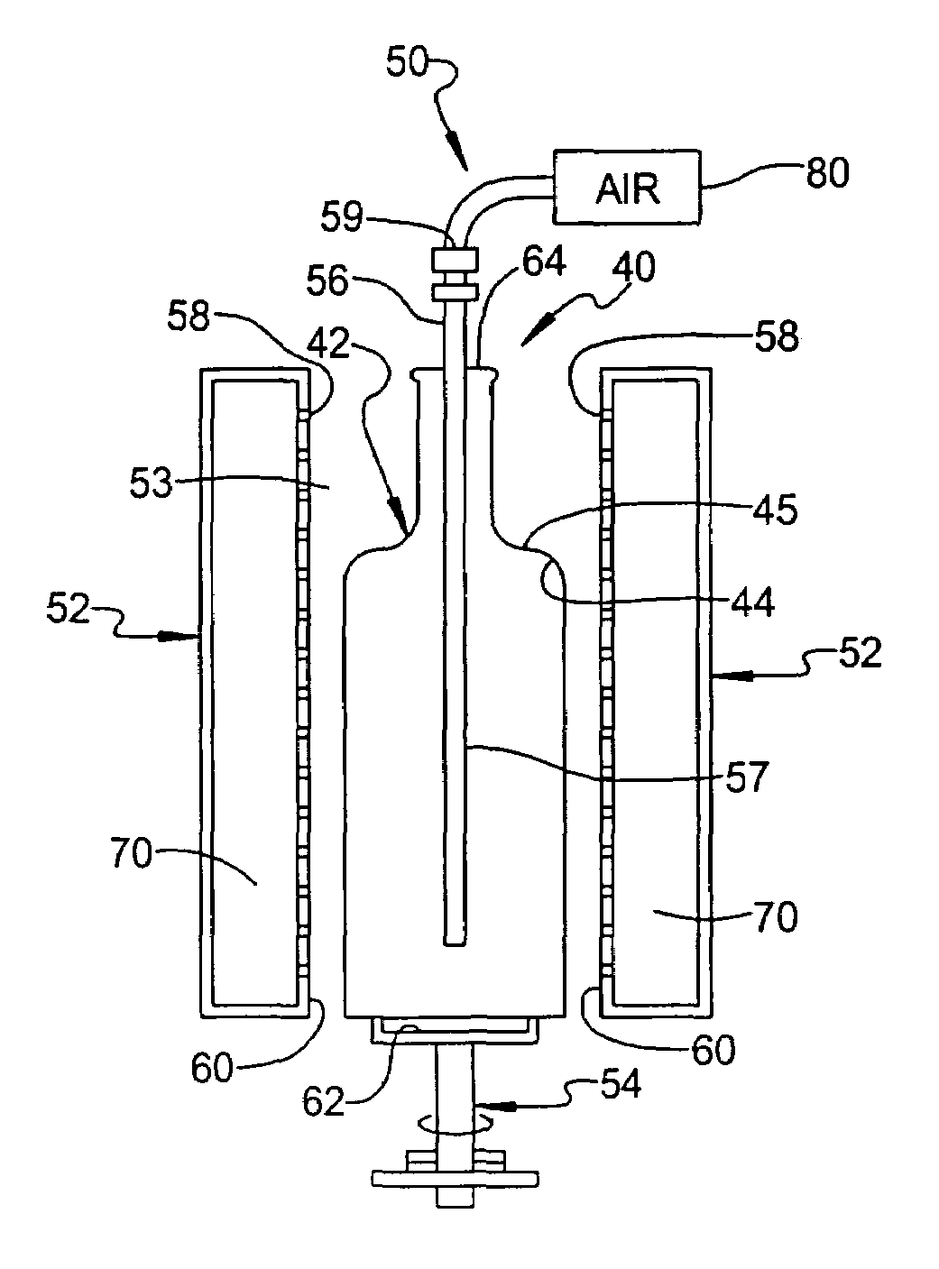
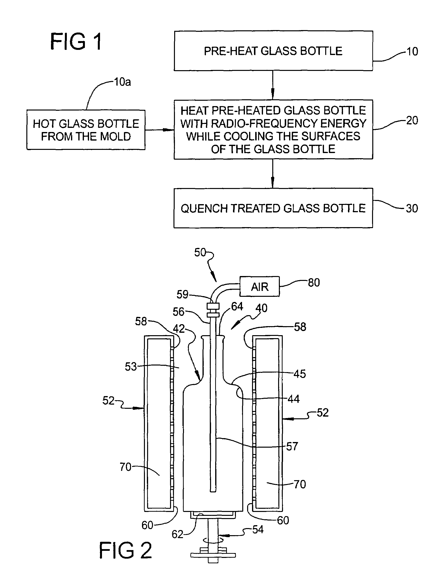
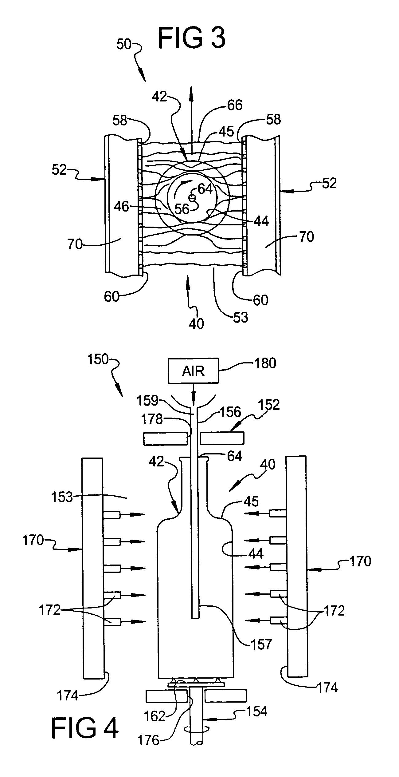
[0019]Referring to FIG. 1, one embodiment of a method, according to the present invention, is shown for tempering a glass container. The method includes first, second, and third steps, 10, 20, 30, respectively. The method can be employed in tempering any suitable glass container such as a bottle, tumbler, or jar. In the system and method shown in the figures and described below, a glass bottle 40 is tempered as shown in FIGS. 2 and 3. However, it should be appreciated that the system and method can be used in connection with any suitable glass container or object. It should be appreciated that the glass, generally indicated at 42, of the bottle 40 is illustrated in FIGS. 2 and 3. It should also be appreciated that the glass 42 of the bottle 40 illustrated defines two major surfaces, namely an inner surface 44 and an outer surface 45, but the glass container could include any suitable number and shape of major surfaces.

[0020]The method includes a first step 10a of receiving a hot gl...


PUM

PropertyMeasurementUnit
temperatureaaaaaaaaaa

Abstract

A system and method is provided for tempering a glass container. The method includes the steps of pre-heating the glass container to a first predetermined temperature. The method also includes the steps of applying radio-frequency energy to the pre-heated glass container to heat the glass container to a second predetermined temperature and, after a predetermined amount of time, simultaneously cooling at least one surface of the heated glass container to a third predetermined temperature to treat the glass container. The method further includes the steps of, after a predetermined amount of time, quenching the treated glass container to a fourth predetermined temperature to produce a tempered glass container.

Description

CROSS-REFERENCE TO RELATED APPLICATION[0001]The present application claims the priority date of copending U.S. Provisional Patent Application Ser. No. 60 / 517,768, filed Nov. 6, 2003, and is a continuation-in-part of U.S. patent application Ser. No. 10 / 247,386, filed Sep. 19, 2002, now U.S. Pat. No. 6,826,929 and entitled “System and Method for Simultaneously Heating and Cooling Glass to Produce Tempered Glass.”BACKGROUND OF THE INVENTION[0002]1. Field of the Invention[0003]The present invention relates generally to glass containers and, more particularly, to a system and method for tempering glass containers such as bottles, tumblers, and jars.[0004]2. Description of the Related Art[0005]Tempered glass is generally defined as glass (e.g., annealed or ordinary) that has been pre-stressed by heating it to a temperature at or above its softening point and forcing the glass to suddenly and rapidly quench under carefully controlled conditions. This tempering process produces tempered gla...

Claims


Application Information

Patent Timeline
Patent Type & Authority Patents(United States)
IPC IPC(8): C03B27/00C03B27/04C21D1/00C21D1/04C21D1/10
CPCC03B27/06C03B29/02C03B27/062
Inventor BOAZ, PREMAKARAN T.
Owner BOAZ PREMAKARAN T
Learn More