Tree stump grinding teeth

a technology for stumps and stumps, applied in special profiling/shaping machines, flat surfacing machines, profiling/shaping machines, etc., can solve the problems of one or more grinding teeth breaking off and/or aging, and the replacement of grinding teeth is often a time-consuming process

Active Publication Date: 2010-04-13
GOSSETT JOHNNY
View PDF6 Cites 13 Cited by
  • Summary
  • Abstract
  • Description
  • Claims
  • Application Information

AI Technical Summary

Benefits of technology

[0009]The present invention is directed to tree stump grinding teeth for use in tree stump grinding wheel assemblies and to tree stump grinding wheel assemblies that comprise one or more of such grinding teeth. In a preferred embodiment of the invention, the tree stump grinding tooth comprises a mounting base having a substantially flat surface from which one or more cleats project. The cleats are adapted to be received in corresponding bores formed in the wheel. A resilient impact pad is positioned between the mounting base of the grinding tooth and the wheel. The resilient impact pad protects the surface of the wheel from impact forces applied to the grinding tooth.

Problems solved by technology

During tree stump removal operations, the grinding teeth are subjected to very large impact and abrading forces.
Over time, these forces can cause one or more of the grinding teeth to break off and / or to wear out.
Replacement of grinding teeth is often a time consuming process because the radial projection of each grinding tooth must be positioned in a predetermined optimal orientation before it is fastened to the wheel.
Thus, if the impact force applied to the grinding tooth were greater than the shear strength of the bolts, the bolts would fail and the grinding tooth would shear away from the wheel.
The loss of mass caused by the shearing away of one or more grinding teeth from the wheel could cause the wheel to become unbalanced, which could create potentially damaging vibration in the grinding machine.
Another drawback with the use of a grinding wheel assembly and grinding teeth such as disclosed in Bowling is that the holes bored in the wheel to receive the bolts are exposed to the risk of damage due to impact forces imparted to the teeth, which can be communicated through the bolts to the holes bored into the wheel.
This can cause the holes bored into the wheel to become deformed and otherwise compromised.
Consequently, the fit and / or orientation of replacement grinding teeth will not be optimal, and replacement grinding teeth may wear prematurely and / or become more readily dislodged from the wheel.
Yet another drawback with the use of the grinding wheel assembly and grinding teeth such as disclosed in Bowling is that the side surfaces of the wheel are exposed to the risk of damage due to impact forces translated through the grinding teeth.
The impact force imparted to the tooth can cause the at least one substantially flat surface of the mounting base in direct contact with the wheel to dent, gouge or otherwise create surface imperfections in the wheel.
Once the surface of the wheel has been damaged, it can be very difficult to properly mount replacement grinding teeth to the wheel.
In addition, moisture can wick between grinding tooth and the wheel, which can promote rust and / or corrosion of the wheel, grinding teeth and / or bolts.

Method used


Image

  • Tree stump grinding teeth
  • Tree stump grinding teeth
  • Tree stump grinding teeth

Examples


Embodiment Construction

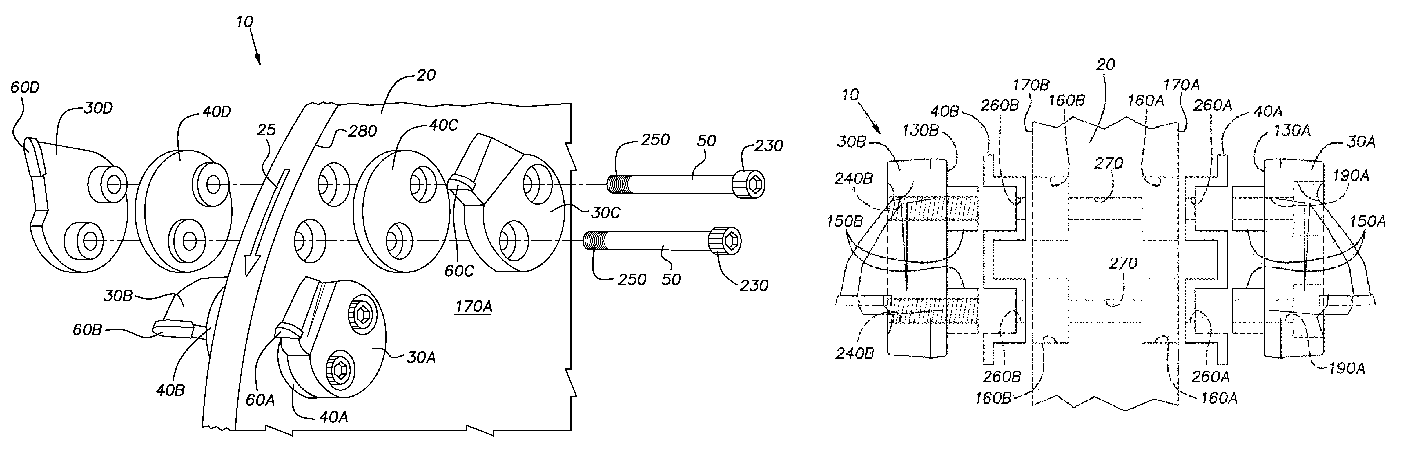
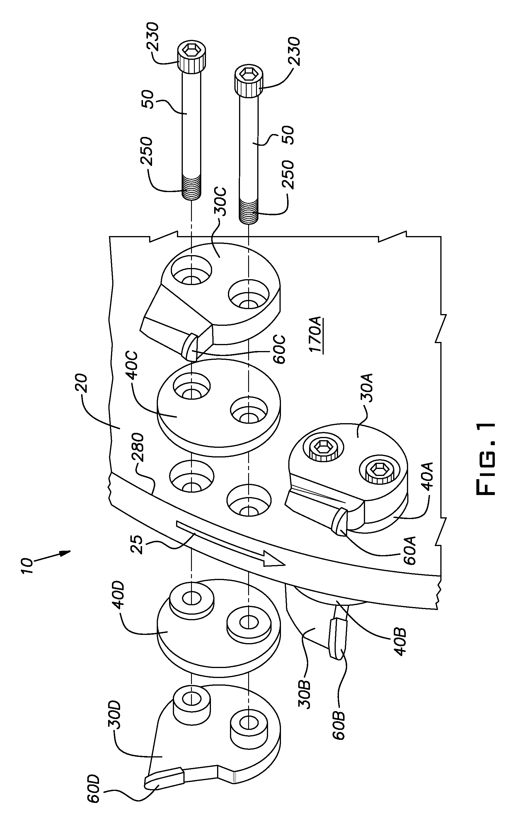
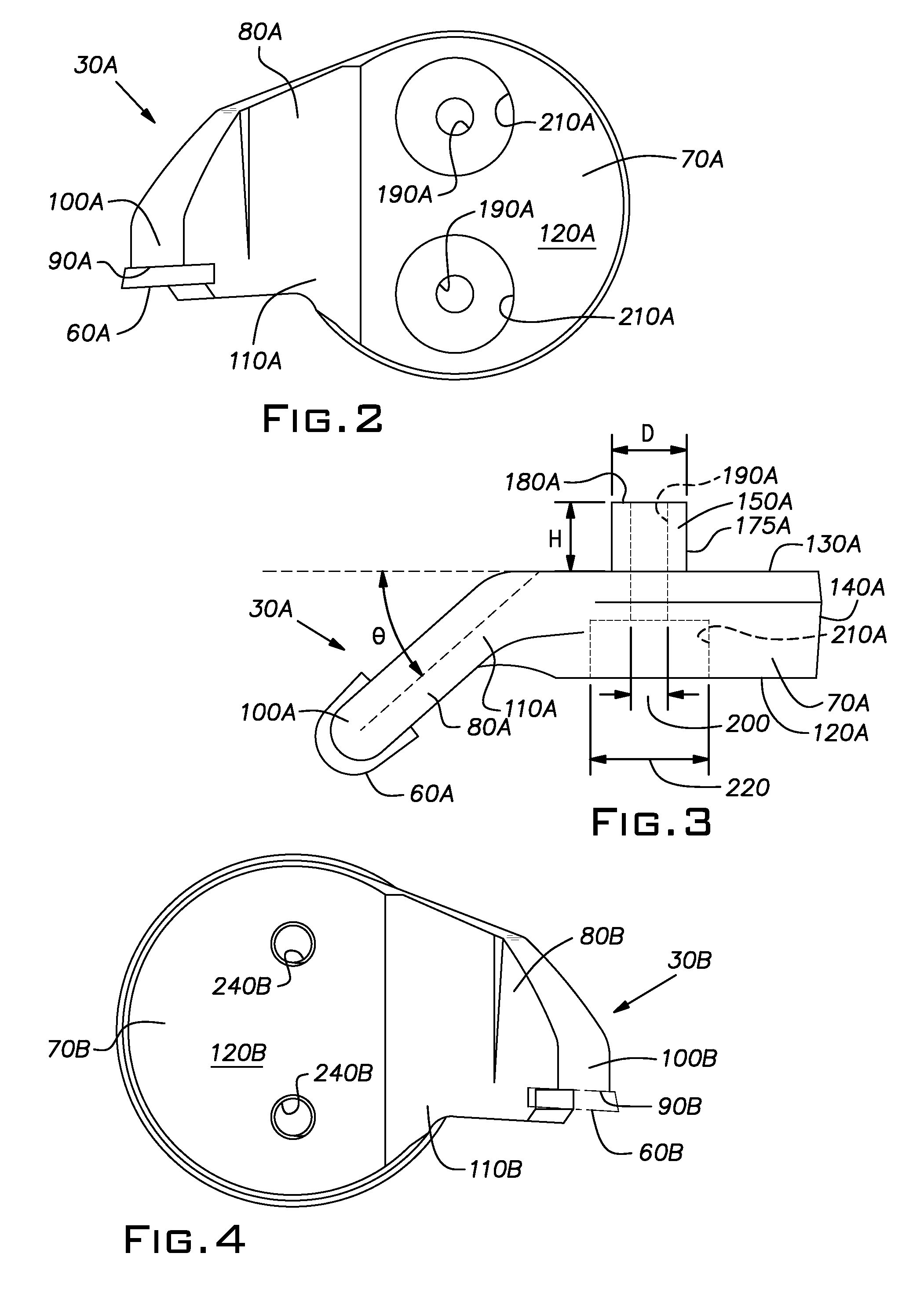
[0027]Referring now to the drawings, wherein like reference numerals have been used for similar elements throughout, FIG. 1 shows a partially exploded perspective view of one preferred embodiment of a tree stump grinding wheel assembly 10 according to the invention. This view shows a portion of a substantially vertical, rotatable wheel 20, a plurality of grinding teeth 30A, 30B, 30C, 30D, a plurality of impact pads 40A, 40B, 40C, 40D and a plurality of fasteners 50. The grinding teeth 30A, 30B, 30C, 30D are fastened in pairs to the wheel 20 using the fasteners 50, with the impact pads 40A, 40B, 40C, 40D positioned between the grinding teeth 30A, 30B, 30C, 30D and the wheel 20.

[0028]The tree stump grinding wheel assembly 10 according to the invention is adapted to be mounted to a stump grinding machine (not shown) that rotates the wheel assembly 10 at relatively high speed in a forward direction relative to the stump grinding machine (i.e., in the direction shown by arrow 25 on the p...


PUM


Abstract

Tree stump grinding teeth for use in tree stump grinding wheel assemblies and tree stump grinding wheel assemblies that include one or more such grinding teeth. In the preferred embodiment of the invention, the grinding tooth includes a mounting base having a substantially flat surface from which a plurality of cleats project. The cleats are adapted to be received in corresponding bores formed in the wheel. A resilient impact pad is positioned between the mounting base of the grinding tooth and the wheel. The resilient impact pad protects the surface of the wheel from impact forces applied to the grinding tooth.

Description

BACKGROUND OF INVENTION[0001]1. Field of Invention[0002]The present invention relates to tree stump grinding teeth and to tree stump grinding wheel assemblies that include the same.[0003]2. Description of Related Art[0004]Conventional tree stump grinding machines include a tree stump grinding wheel assembly that comprises a vertically oriented wheel having a plurality of grinding teeth (which are sometimes also referred to in the art as “cutting teeth”) mounted on both side surfaces thereof. The wheel is typically mounted on an extension arm or boom of a grinding machine, which rotates the wheel at relatively high speed in a forward direction relative to the grinding machine. An operator of the grinding machine moves the rotating wheel in plunging and sweeping motions relative to a tree stump to be removed, which causes the grinding teeth mounted thereon to make contact with the tree stump. The grinding teeth grind mounted to the rotating wheel impact against the tree stump and ther...

Claims


Application Information

Patent Timeline
Patent Type & Authority Patents(United States)
IPC IPC(8): A01G23/06
CPCA01G23/067
Inventor GOSSETT, JOHNNY
Owner GOSSETT JOHNNY
Why Eureka
Try Eureka