Cab structure of construction machine

a construction machine and cab structure technology, applied in the direction of roofs, doors, pedestrian/occupant safety arrangements, etc., can solve the problems of narrow opening width of sliding doors, difficult to provide a guide portion, and more difficult to form a recess in pipe-shaped members disposed on the front side of the doorway

Active Publication Date: 2010-04-13
KOMATSU LTD
View PDF7 Cites 11 Cited by
  • Summary
  • Abstract
  • Description
  • Claims
  • Application Information

AI Technical Summary

Benefits of technology

[0009]According to the cab structure of a construction machine, the guide portion is provided in the position ranging from the first position that is located frontward from the second column portion and rearward from the first column portion to the second position that is located rearward from the second column portion. Therefore, it is possible to avoid interference with the first column portion and it is also possible to secure the entire length of the guide portion to be long. With the above configuration, it is possible to secure the opening width of the sliding door to be wide.
[0011]According to the cab structure of a construction machine, the upper end of the second column portion is fixed to the lower surface of the first support member that supports the sliding door. Therefore, load applied by the sliding door is supported by the second column portion through the first support member. Accordingly, it is possible to further reliably support the sliding door.
[0013]According to the cab structure of a construction machine, the guide portion passes through the position right above the second column portion. Therefore, it is possible to avoid interference with the second column portion. In addition, it is possible to prevent the cab from externally bulging, compared to a case that the guide portion is provided to pass through the outside of the second column portion. Therefore, it is possible to compactly form the cab.
[0016]According to the cab structure of a construction machine, the first guide roller is supported by the first support member. Accordingly, load applied by the sliding door in the vertical direction is supported. In addition, the second guide roller is guided by the guide portion. Accordingly, movement of the sliding door in the horizontal direction is restricted, and the sliding door is allowed to move along the lateral surface of the cab. Furthermore, the first support member and the second support member are provided along the beam. Accordingly, it is possible to easily provide the support structure of a sliding door without performing complicated processing with respect to the beam portion.
[0018]In the cab structure of a construction machine, the lateral surface on which the sliding door is provided is formed in a curved shape that externally bulges. Accordingly, it is possible to reduce the swivel radius during swiveling of the upper swivel.
[0021]According to the cab structure of a construction machine, the guide portion is provided in the position ranging from the first position that is located frontward from the middle column member and rearward from the first column portion to the second position that is located rearward from the middle column member. Accordingly, it is possible to avoid interference with the first column portion and it is also possible to secure the entire length of the guide portion to be long. With the above configuration, it is possible to secure the opening width of the sliding door to be wide.

Problems solved by technology

Therefore, it is difficult to provide a guide portion in a state that the guide portion reaches the front end portion of the cab.
However, in the above described cab structure formed by the pipe-shaped members, it is more difficult to form a recess portion in the pipe-shaped members disposed on the front side of the doorway, compared to the sheet metal members.
As a result, there is a possibility that the opening width of the sliding door becomes narrow.

Method used


Image

  • Cab structure of construction machine
  • Cab structure of construction machine
  • Cab structure of construction machine

Examples


Embodiment Construction

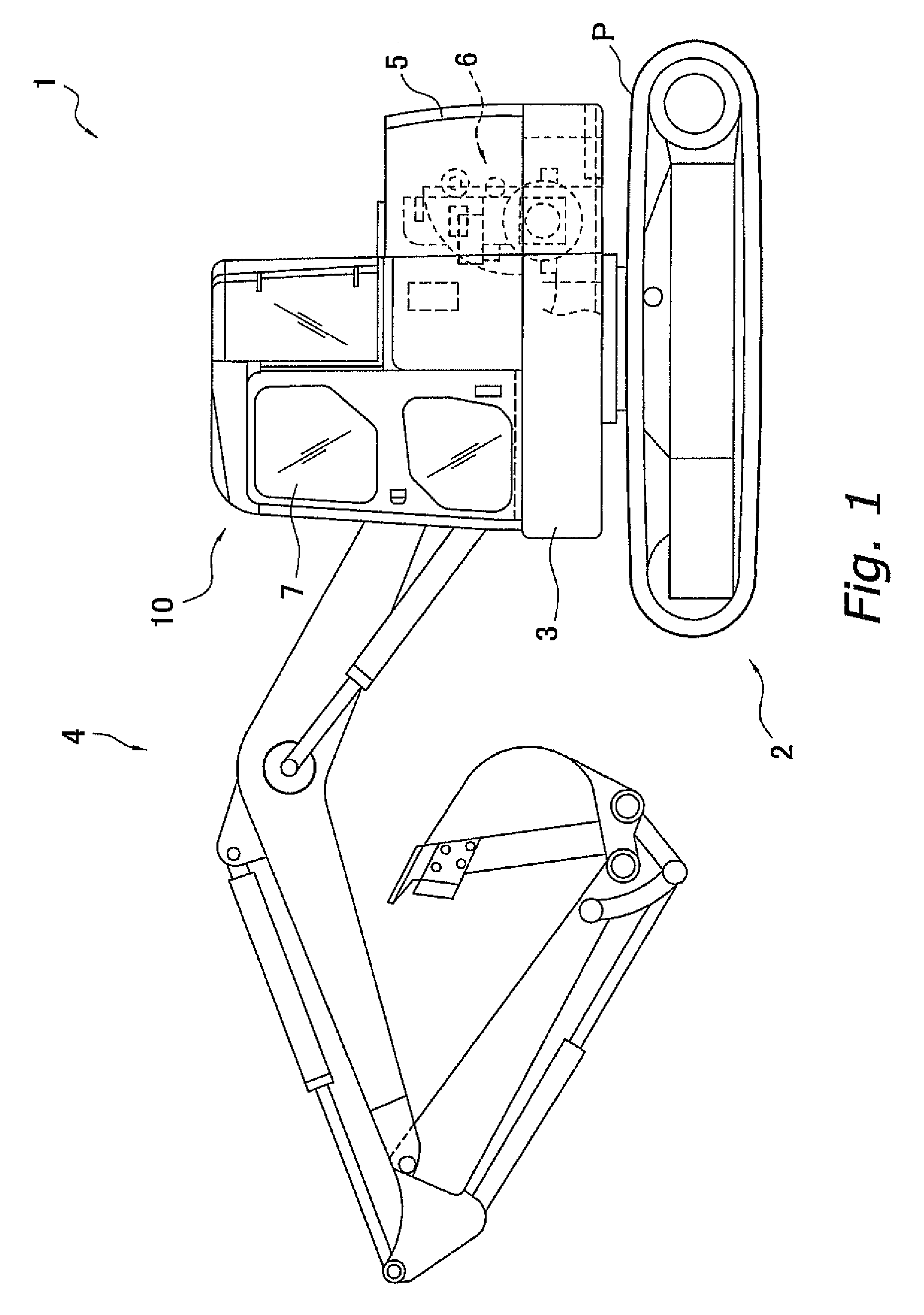
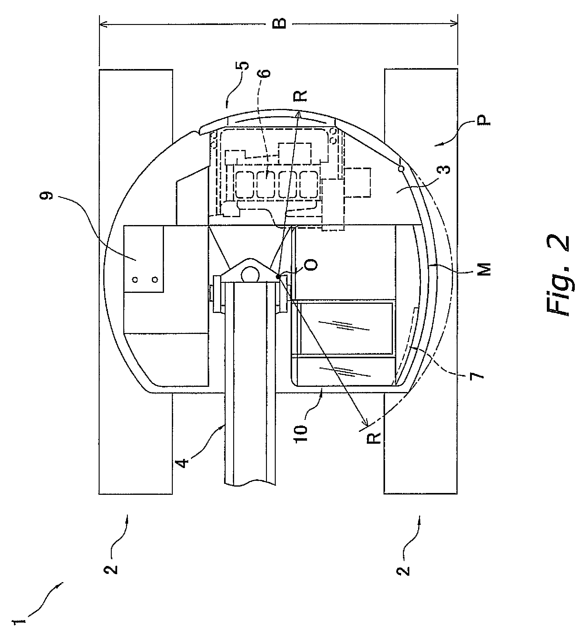
[0033]FIGS. 1 and 2 illustrate a hydraulic excavator 1 to which a cab structure of a construction machine in accordance with an embodiment of the present invention is applied. FIG. 1 is a lateral view of the hydraulic excavator 1, and FIG. 2 is a top view of the hydraulic excavator 1. Note that the terms “right and left,”“back and forth,” and “front side and rear side” are used to indicate directions based on the direction that an operator being seated within a cab 10 faces.

(Entire Configuration of Hydraulic Excavator 1)

[0034]The hydraulic excavator 1 in accordance with the present embodiment includes a base carrier 2, a swivel platform 3, an operating machine 4, a counterweight 5, an engine 6, a machine room 9, and the cab 10. In addition, the hydraulic excavator 1 is a small rear-swivel type hydraulic excavator in which the swivel radius R (see FIG. 2) of the machine excluding the operating machine 4 is configured to be a predetermined value or less and the amount of a portion of ...


PUM


Abstract

The frame body is formed by a plurality of pipe-shaped members including a first column portion, a beam portion, the front end portion of which is connected to the upper end portion of the first column portion, and a middle column member that is disposed rearward from the first column portion. The upper guide portion is provided along a beam portion in a position ranging from a first position to a second position. Here, the first position is located frontward from the middle column member and rearward from the first column portion, and the second position is located rearward from the middle column member.

Description

CROSS-REFERENCE TO RELATED APPLICATIONS[0001]This U.S. National stage application claims priority under 35 U.S.C. §119(a) to Japanese Patent Application No. 2005-258522, filed in Japan on Sep. 6, 2005. The entire contents of Japanese Patent Application No. 2005-258522 are hereby incorporated herein by reference.TECHNICAL FIELD[0002]Present invention relates to a cab structure of a construction machine.BACKGROUND ART[0003]Recently, construction machines have been commonly provided with a cab structure that is configured to protect an operator when the machines fall down. Accordingly, the roll over protective structure (ROPS) performance has been considered as an important factor. For example, a Japanese Patent Application Publication No. JP-A-2004-224083 discloses a cab structure of a construction machine, which is a frame structure formed by assembling a variety of pipe-shaped members in a basket shape. According to this type of structure, it is possible to remarkably enhance stiffn...

Claims


Application Information

Patent Timeline
Patent Type & Authority Patents(United States)
IPC IPC(8): B60R21/13
CPCB60J5/0487E02F9/163B62D33/0617B60J5/062B60J5/06B62D25/08B62D33/06E02F9/16
Inventor TSUKAMOTO, DAISUKE
Owner KOMATSU LTD
Why Eureka
Try Eureka