Back end thin film capacitor having both plates of thin film resistor material at single metallization layer

a technology of thin film resistor and back end, which is applied in the field of back end ” thin film capacitor structure and methods, can solve the problems of large chip area, unsuitable, unmet need for a practical way, etc., and achieve the effect of improving the integrated circuit structur

Active Publication Date: 2010-04-13
TEXAS INSTR INC
View PDF8 Cites 10 Cited by
  • Summary
  • Abstract
  • Description
  • Claims
  • Application Information

AI Technical Summary

Benefits of technology

[0012]It is another object of the invention to provide an improved integrated circuit structure and method for integrating back end capacitors into integrated circuits with already-formed integrated circuit substructures including transistors and / or other integrated circuit elements such as diffused resistors and / or polycrystalline resistors using the same manufacturing process utilized for integrating back end thin film resistors into such integrated circuits.

Problems solved by technology

Back end capacitors of the type shown in FIG. 1 typically require a large amount of chip area.
“Poly-capacitors”, including poly-oxide-metal and poly-oxide-poly capacitors are well-known in the art, but are not considered to be suitable as “back end” capacitors because they must be formed in conjunction with formation of the transistors and therefore “compete” with the transistors for unavailable chip area.
There also is an unmet need for a practical way of providing capacitors and / or resistors in integrated circuits which do not “compete” for available chip area in which transistors can be formed.

Method used


Image

  • Back end thin film capacitor having both plates of thin film resistor material at single metallization layer
  • Back end thin film capacitor having both plates of thin film resistor material at single metallization layer
  • Back end thin film capacitor having both plates of thin film resistor material at single metallization layer

Examples


Embodiment Construction

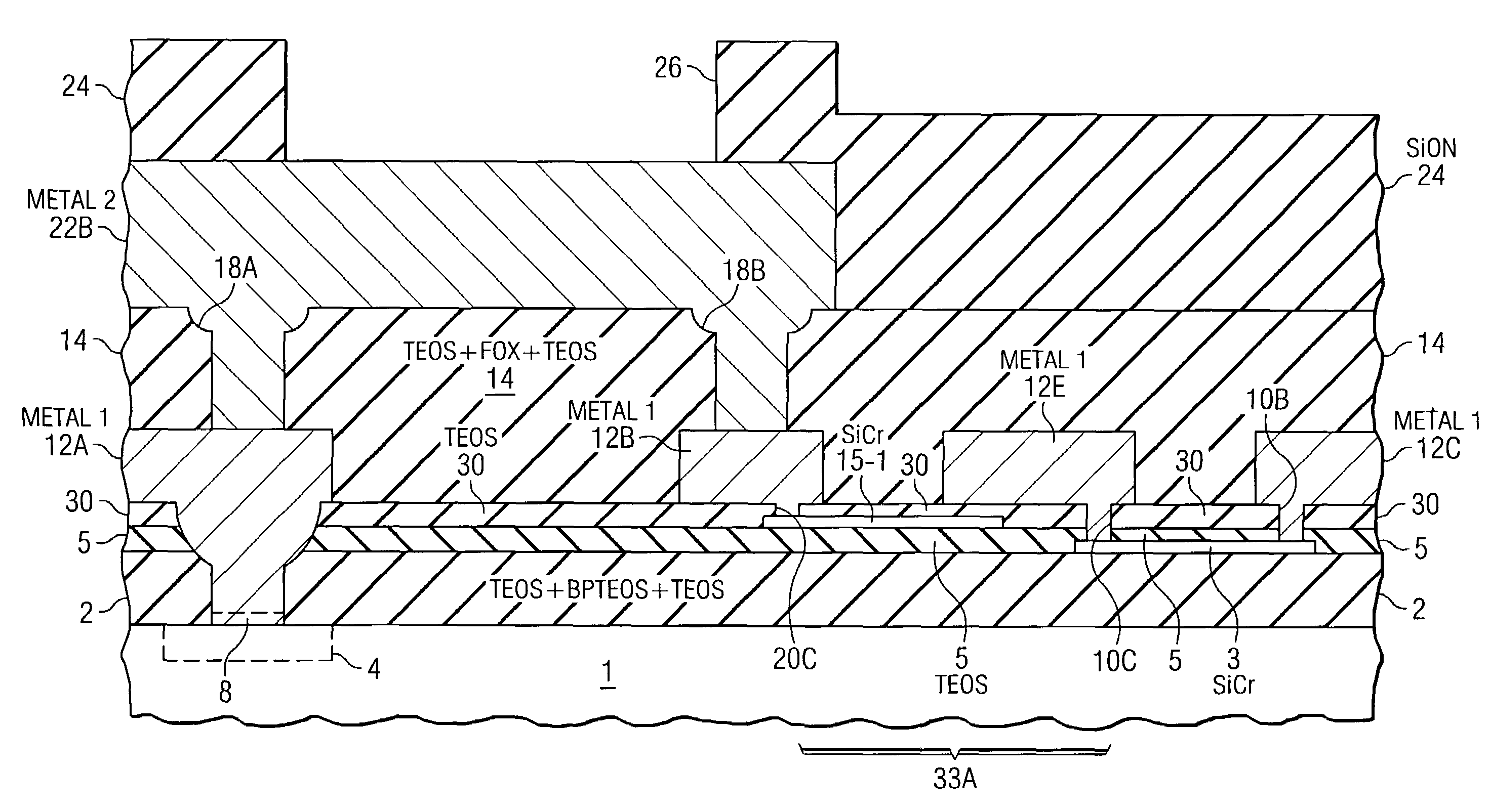
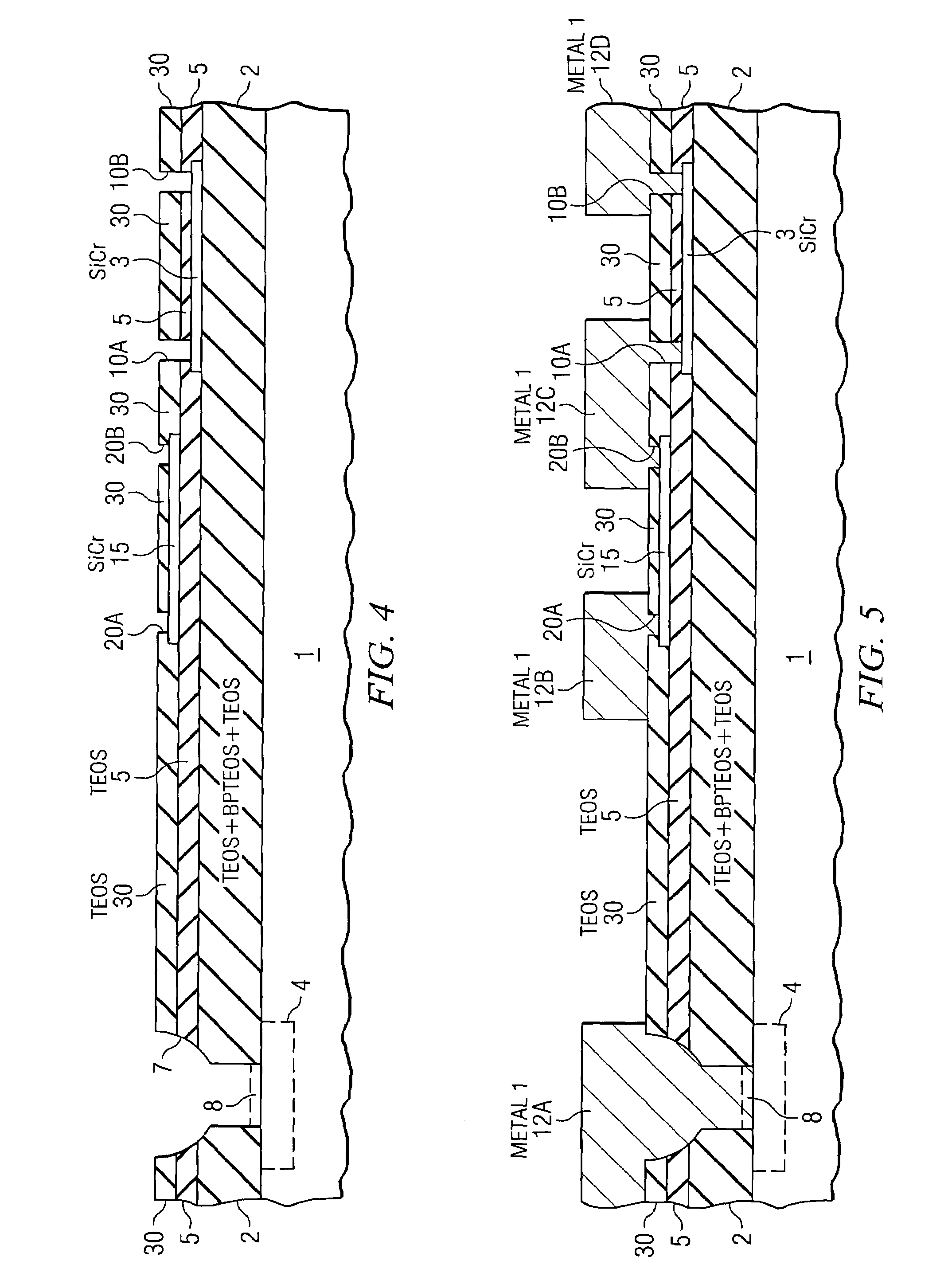
[0027]FIGS. 2-9 illustrate a sequence of the basic processing operations which can be used for integrating various kinds of “back end” thin film capacitors and / or various kinds of “back end” thin film resistors into a integrated circuit, wherein the thin film resistive materials can have the same or different sheet resistances and TCRs. The back end thin film capacitors and resistors can be interconnected by a single level of interconnect metallization.

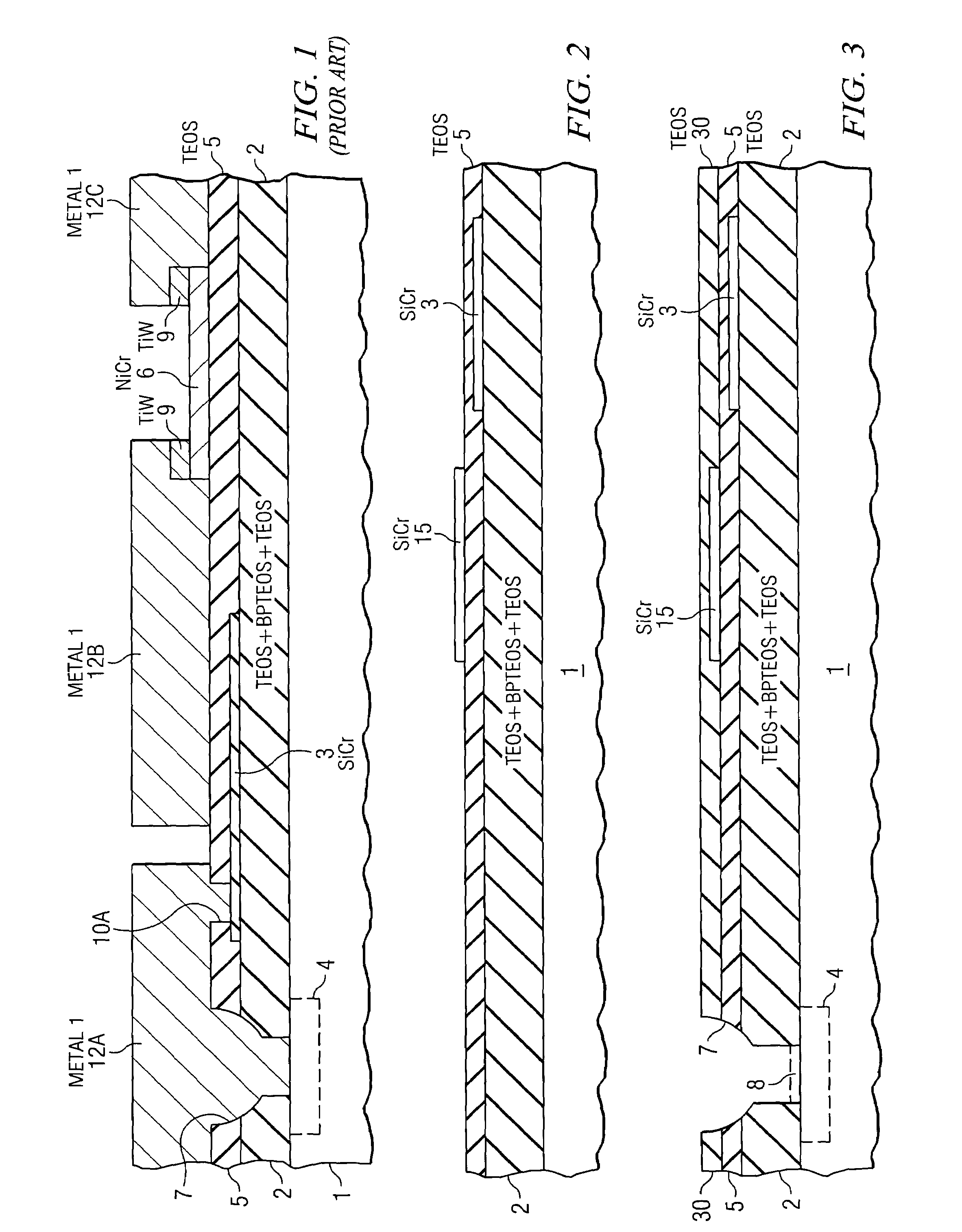
[0028]Referring to FIG. 2, a starting silicon substrate 1 has a standard pre-metal dielectric layer 2 including a first TEOS (tetraethylorthosilicate) layer on silicon substrate 1, a BPTEOS (Boron-Phosphorus TEOS) layer on the first TEOS sublayer, and a second TEOS layer on the BPTEOS sublayer. Typically, various active devices such as bipolar and / or MOS transistors have already been formed in region 4 of substrate 1.

[0029]A thin layer 3 of sichrome (SiCr) having a sheet resistance, typically in the range from 30 to 2000 ohms per squa...


PUM


Abstract

An integrated circuit back end capacitor structure includes a first dielectric layer on a substrate, a thin film bottom plate on the first dielectric layer, and a second dielectric layer on the first dielectric layer and the bottom plate, and a thin film top plate disposed on the second dielectric layer. The thin film top plate and bottom plate are composed of thin film resistive layers, such as sichrome, which also are utilized to form back end thin film resistors having various properties. Interconnect conductors of a metallization layer contact the top and bottom plates through corresponding vias.

Description

BACKGROUND OF THE INVENTION[0001]The present invention relates generally to practical “back end” thin film capacitor structures and methods, and also to integrating such back end thin film capacitors into processes and methods for making “back end” thin film resistors. (The term “back end” is used herein to describe integration of components, including thin film capacitors and back end thin film resistors, onto a partially fabricated integrated circuit structure after transistors and polycrystalline silicon structures have already been formed therein. So-called “front end” processes typically include steps performed at a temperatures of 600 to 700 degrees Centigrade, whereas at the present state-of-the-art, “back end” processes typically include only steps performed at temperatures less than roughly 450 degrees Centigrade.)[0002]FIG. 1 shows a prior art structure in which various transistors have been formed, using conventional techniques, in a region 4 of a starting silicon substra...

Claims


Application Information

Patent Timeline
Patent Type & Authority Patents(United States)
IPC IPC(8): H01L29/00
CPCH01L27/016H01L28/60H01L28/20
Inventor BEACH, ERIC W.
Owner TEXAS INSTR INC
Why Eureka
Try Eureka