Vehicle mounted surveillance system

a surveillance system and vehicle technology, applied in the field of surveillance systems, can solve the problems of inability to maintain surveillance, more problems with mobile application use of such surveillance, and individuals' limited means, and achieve the effect of conceiving the image stabilizing mechanism

Inactive Publication Date: 2010-04-13
JOHNSON DOUGLAS M
View PDF27 Cites 252 Cited by
  • Summary
  • Abstract
  • Description
  • Claims
  • Application Information

AI Technical Summary

Benefits of technology

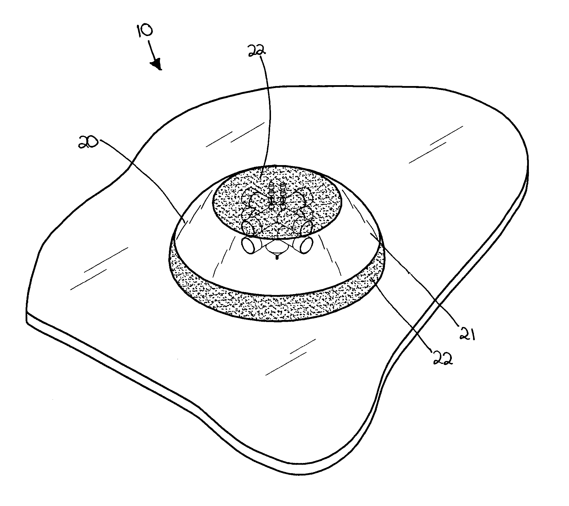
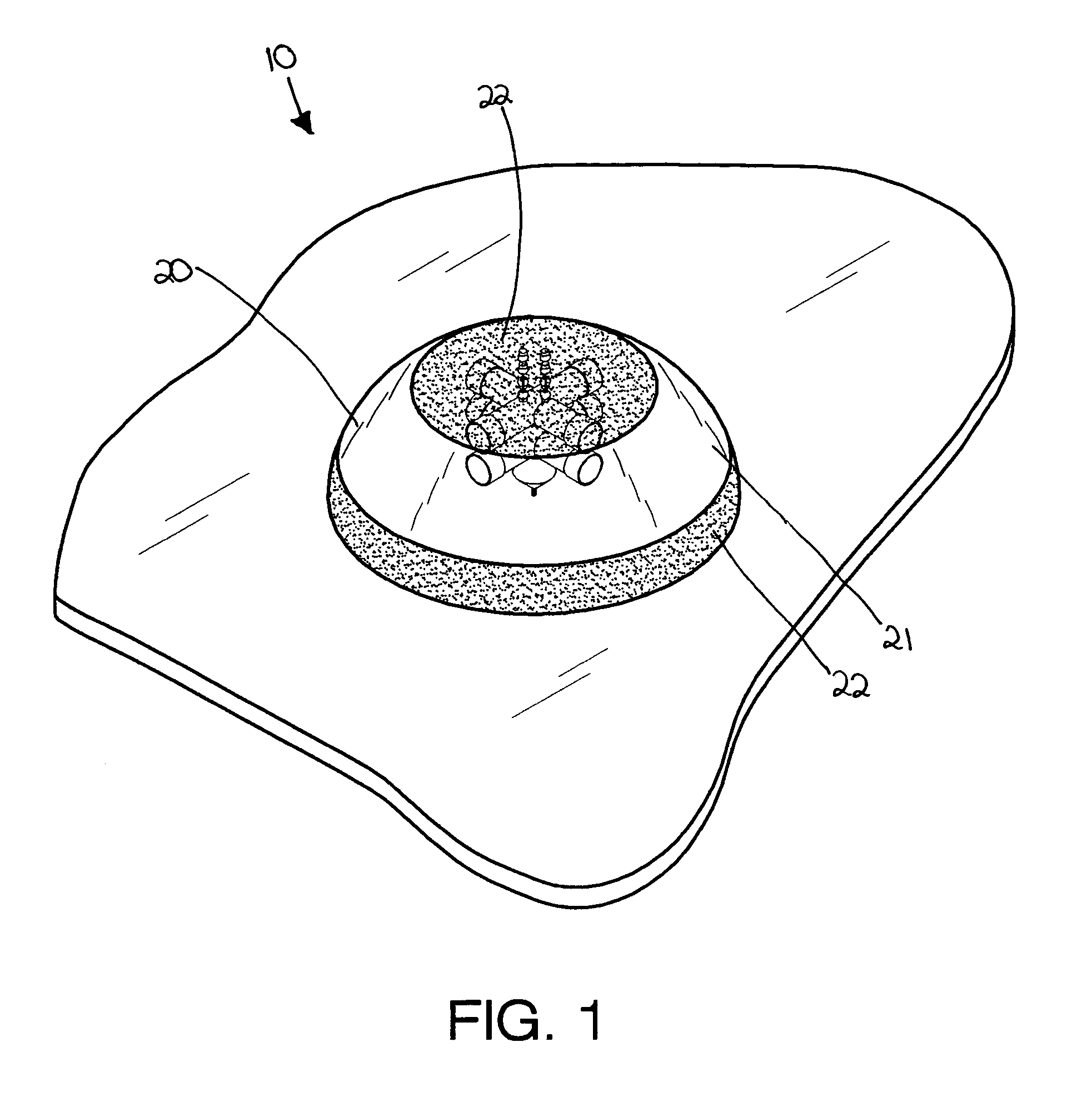
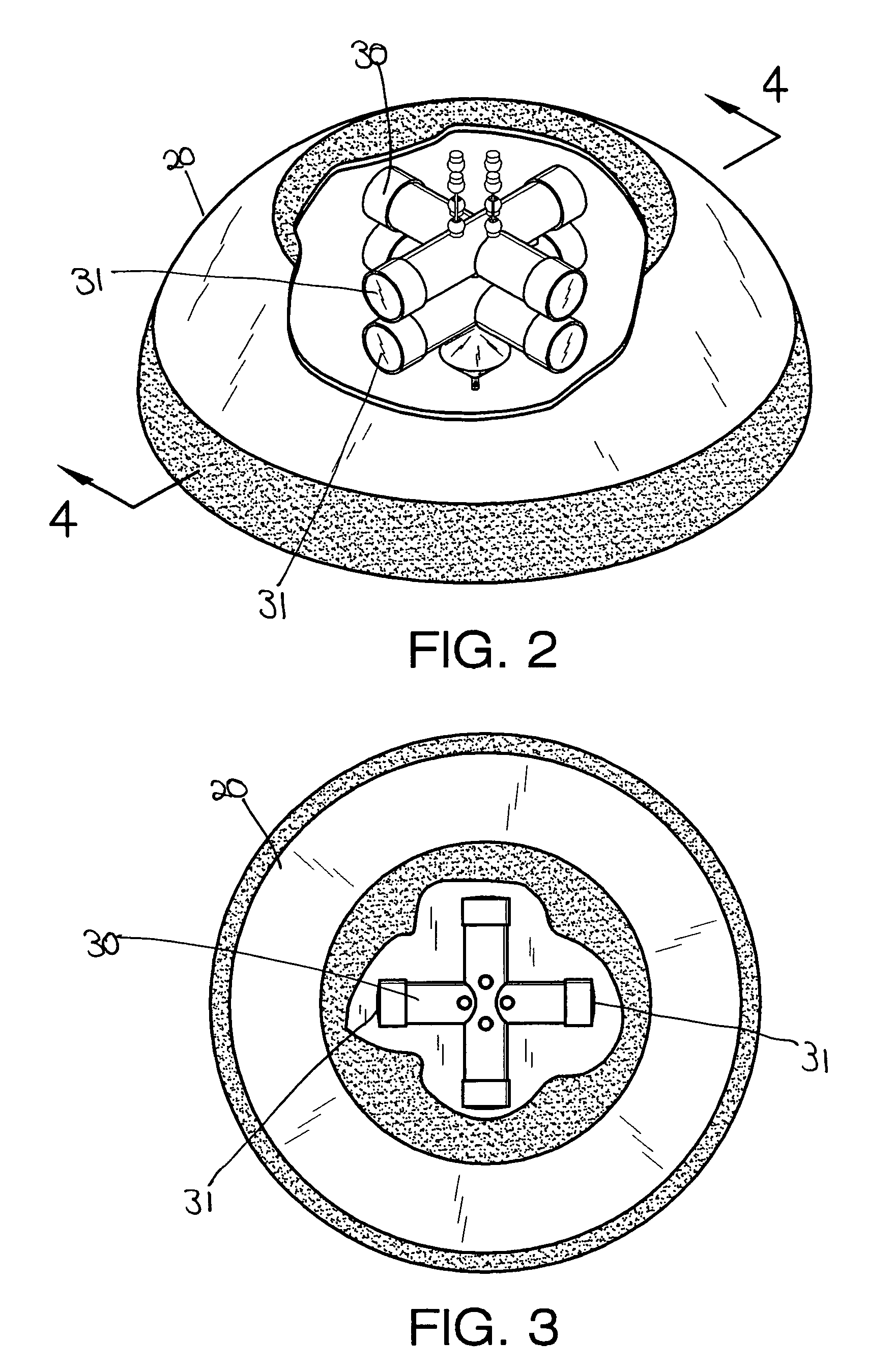
[0013]In view of the foregoing background, it is therefore an object of the present invention to provide a vehicle mounted surveillance system. These and other objects, features, and advantages of the invention are provided by a security system for recording information external and proximate a vehicle and delivering such information to a remote location. Such a system includes a housing with a generally dome shape, which is removably attachable to a select portion of a vehicle. The housing is preferably formed from plastic or glass and has a translucent portion and a plurality of opaque portions spaced thereabout. Such a translucent portion allows a plurality of cameras (described herein below) to view exterior of a vehicle. Conversely, the plurality of opaque portions help conceal the image stabilizing mechanism from the public.

Problems solved by technology

Government agencies too sometimes need to maintain surveillance on the operation of their law enforcement vehicles, especially with the heightened threat of terrorist activities.
As opposed to organizations with substantial resources, individuals have a far more limited means available to them for this purpose.
While the above-described surveillance systems have become increasingly common at permanent fixed locations, the use of such surveillance in mobile applications has been more problematic.
It can prove difficult and unreliable to store the images on board a vehicle since they are prone to tampering.

Method used


Image

  • Vehicle mounted surveillance system
  • Vehicle mounted surveillance system
  • Vehicle mounted surveillance system

Examples


Embodiment Construction

[0036]The present invention will now be described more fully hereinafter with reference to the accompanying drawings, in which a preferred embodiment of the invention is shown. This invention may, however, be embodied in many different forms and should not be construed as limited to the embodiment set forth herein. Rather, this embodiment is provided so that this application will be thorough and complete, and will fully convey the true scope of the invention to those skilled in the art. Like numbers refer to like elements throughout the figures.

[0037]The system of this invention is referred to generally in FIGS. 1-5 by the reference numeral 10 and is intended to provide security monitoring through a mounted surveillance system. It should be understood that the system 10 may be retrofitted on all types of vehicles for monitoring threatening activities such as theft, terrorism, and vandalism.

[0038]Referring initially to FIG. 1, the system 10 includes a housing 20 with a generally dome...


PUM


Abstract

A security system for recording information outside a vehicle and delivering such information to a remote location includes a plurality of cameras mounted within a housing with radial lines of sight for providing a panoramic view of the surroundings. The present invention further includes a communication mechanism for transmitting an image to a remote location. A user interface includes one of a hand-operable video phone, personal computer and cellcorder. The present invention further includes an image stabilizing mechanism for maintaining the lines of sight along a linear path. The image stabilizing mechanism is secured to the housing and cameras. Such an image stabilizing mechanism includes a housing that has a motor, a gyro, and a helical spring member, which provide support as the vehicle is in motion.

Description

CROSS REFERENCE TO RELATED APPLICATIONS[0001]Not Applicable.STATEMENT REGARDING FEDERALLY SPONSORED RESEARCH OR DEVELOPMENT[0002]Not Applicable.REFERENCE TO A MICROFICHE APPENDIX[0003]Not Applicable.BACKGROUND OF THE INVENTION[0004]1. Technical Field[0005]This invention relates to a surveillance system and, more particularly, to a vehicle-mounted surveillance system including a stabilizing mechanism for providing a steady image stream during vehicle motion.[0006]2. Prior Art[0007]Very often vehicles are operated by persons other than their owners. In those situations the owners normally have a vested interest in seeing that their vehicles are operated in a safe and prudent manner. For example, the backs of trucks are often marked, “How is my driving? Call (a certain telephone number).” Rental car companies also have an interest in seeing that their cars are not mishandled. Government agencies too sometimes need to maintain surveillance on the operation of their law enforcement vehic...

Claims


Application Information

Patent Timeline
Patent Type & Authority Patents(United States)
IPC IPC(8): H04N7/18H04N5/225H04N7/00
CPCB60R1/00B60R25/102B60R25/305G08B13/19632G08B13/19619G08B13/19626B60R2300/102B60R2300/105B60R2300/302B60R2300/406B60R2300/8073B60R2300/106
Inventor JOHNSON, DOUGLAS M.
Owner JOHNSON DOUGLAS M
Why Eureka
Try Eureka