Universal rotation speed source for aircraft engine

A technology for engines and aircraft, applied in the field of general speed source, can solve problems such as poor versatility and comprehensiveness, impact on support efficiency, poor scalability, etc., achieve obvious military benefits, high speed adjustment accuracy, and improve efficiency

Pending Publication Date: 2017-06-23
NAVAL AERONAUTICAL & ASTRONAUTICAL UNIV PLA +1
View PDF7 Cites 1 Cited by
  • Summary
  • Abstract
  • Description
  • Claims
  • Application Information

AI Technical Summary

Problems solved by technology

Most of the existing speed test equipment is developed for specific models, which are highly targeted, not universal and comprehensive, and relatively poor in function expansion
Once there is a new type of aircraft or a new type of speed equipment is refitted, it is necessary to redevelop the corresponding test equipment, which wastes resources and affects the efficiency of support

Method used


Image

  • Universal rotation speed source for aircraft engine
  • Universal rotation speed source for aircraft engine
  • Universal rotation speed source for aircraft engine

Examples


Embodiment Construction

[0022] In order to make the object, technical solution and advantages of the present invention clearer, the present invention will be further described in detail below in conjunction with specific embodiments and with reference to illustrations. While illustrations of parameters including particular values ​​may be provided herein, it should be understood that parameters need not be exactly equal to the corresponding values, but rather may approximate the values ​​within acceptable error margins or design constraints.

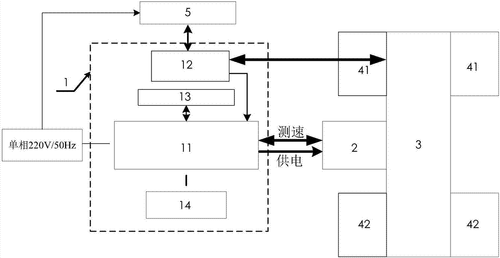
[0023] figure 1 It is a schematic structural diagram of a universal rotational speed source suitable for aircraft engines according to an embodiment of the present invention. Such as figure 1 As shown, it consists of a speed controller (1), a brushless DC motor (2), a speed increasing device (3), a transition connection device (4) and a speed display device (5).

[0024] The speed controller (1) includes a motor control driver (11), a speed measuring mechanis...


PUM


Abstract

The invention provides a universal rotation speed source for an aircraft engine. The universal rotation speed source comprises a brushless direct current motor, a speed increasing device, a rotation speed controller, a rotation speed measuring device, a transition connecting device and a rotation speed display device. The rotation speed controller is composed of a motor control driver, a photoelectric code disc speed measuring mechanism, an external speed setting device and a data setting device. The rotation speed controller is connected with the brushless direct current motor through a cable so as to control the rotation speed and the rotation direction of the brushless direct current motor. The brushless direct current motor is arranged on the main rotating shaft of the speed increasing device. The output shaft of the speed increasing device is driven by a belt wheel transmission mechanism, so that the transformation of the rotation speed is realized. The output shaft of the speed increasing device is connected with the rotation speed measuring device. The rotation speed measuring device is simultaneously connected with the rotation speed controller and the rotation speed display device through cables. On one hand, the actual rotation speed of the output shaft of the speed increasing device is fed back to the rotation speed controller, so that the rotation speed adjustment of the rotation speed controller is facilitated. On the other hand, the actual rotation speed of the output shaft of the speed increasing device is displayed in real time through the rotation speed display device.

Description

technical field [0001] The invention relates to a general rotational speed source suitable for aircraft engines, more specifically, relates to a general rotational speed source suitable for fixed-wing or rotary-wing aircraft engine rotational speed simulation. Background technique [0002] The engine tachometer and the rotor tachometer are important indicating instruments of the aircraft, which directly reflect whether the aircraft engine and the rotor speed system are working normally. Therefore, whether the tachometer can correctly and reliably indicate the corresponding speed is directly related to the flight safety of the aircraft and the completion of the mission. . [0003] At present, the current situation of testing the domestic aircraft speed system is that there is no corresponding speed test equipment due to the equipment of a new type of aircraft or the upcoming equipment of a new type of aircraft. Existing speed test equipment, some due to small power, single s...

Claims


Application Information

Patent Timeline
Patent Type & Authority Applications(China)
IPC IPC(8): G01P21/02
CPCG01P21/02
Inventor 卢建华赵见知高超戴洪德李华平李飞
Owner NAVAL AERONAUTICAL & ASTRONAUTICAL UNIV PLA
Why Eureka
Try Eureka