
Box magazine for a firearm

a box magazine and firearm technology, applied in the field of box magazine for firearms, can solve the problems of always restricted known designs and adversely affecting firing accuracy, and achieve the effects of reducing the risk of damage to the cartridge, reducing the friction of the cartridge, and good wear resistan

Inactive Publication Date: 2010-04-20
STEYR MANNLICHER
View PDF17 Cites 34 Cited by
  • Summary
  • Abstract
  • Description
  • Claims
  • Application Information

AI Technical Summary

Benefits of technology

This solution prevents cartridge deformation during loading, allows for the use of various calibers with a single magazine design, simplifies manufacturing logistics, reduces costs, and enhances user adaptability by enabling modular interchangeability of guide strips.

Problems solved by technology

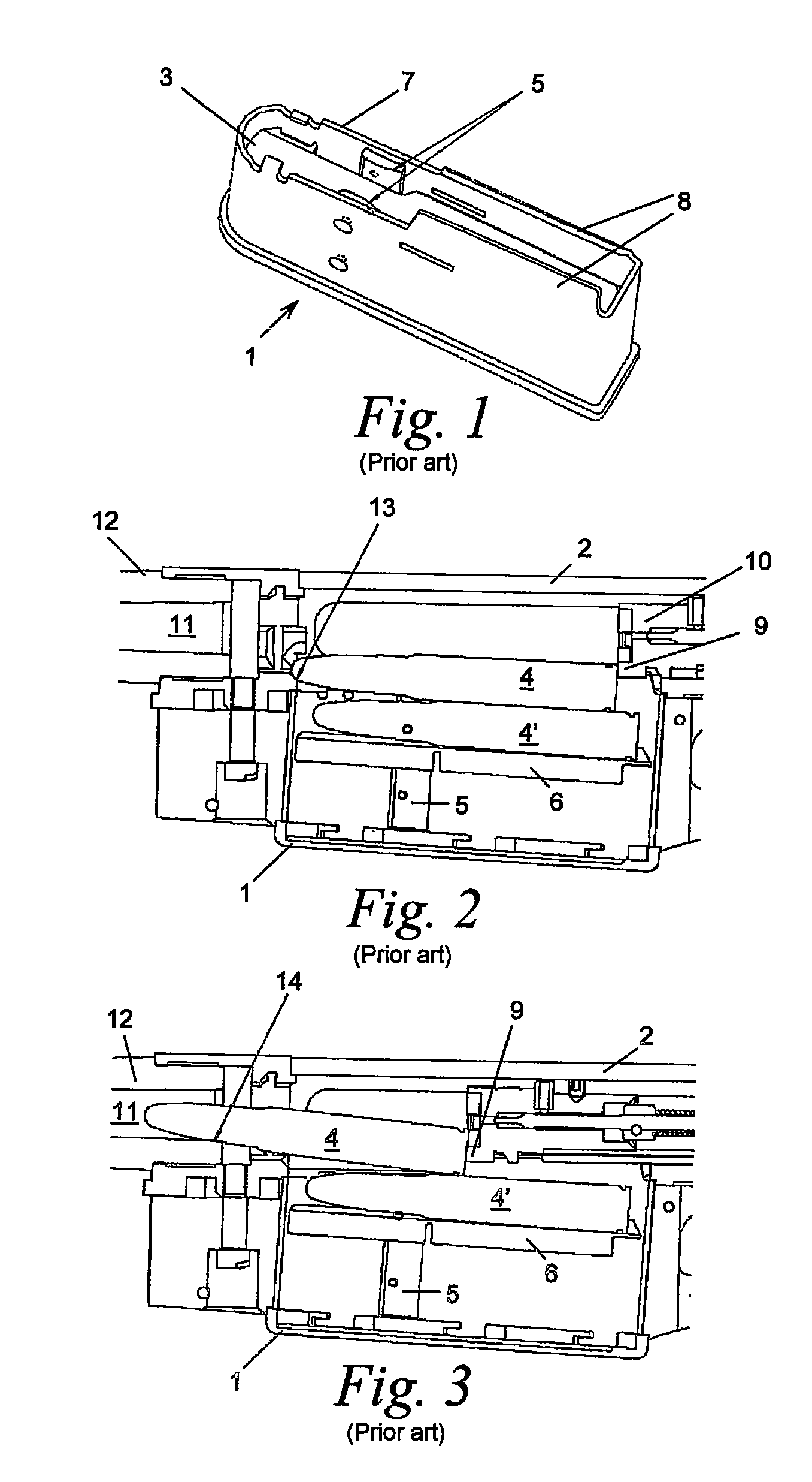
As FIGS. 2 and 3 show, the head or the neck of the cartridge 4 during this process runs on guide edges 13, 14 of the firing chamber 11, which can lead to slight deformation and asymmetry of the cartridge, adversely affecting the firing accuracy.
However, the known designs are always restricted to the specific weapon / magazine / caliber combinations.

Method used


Image

  • Box magazine for a firearm
  • Box magazine for a firearm
  • Box magazine for a firearm

Examples


Embodiment Construction

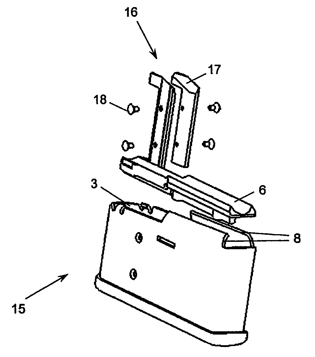
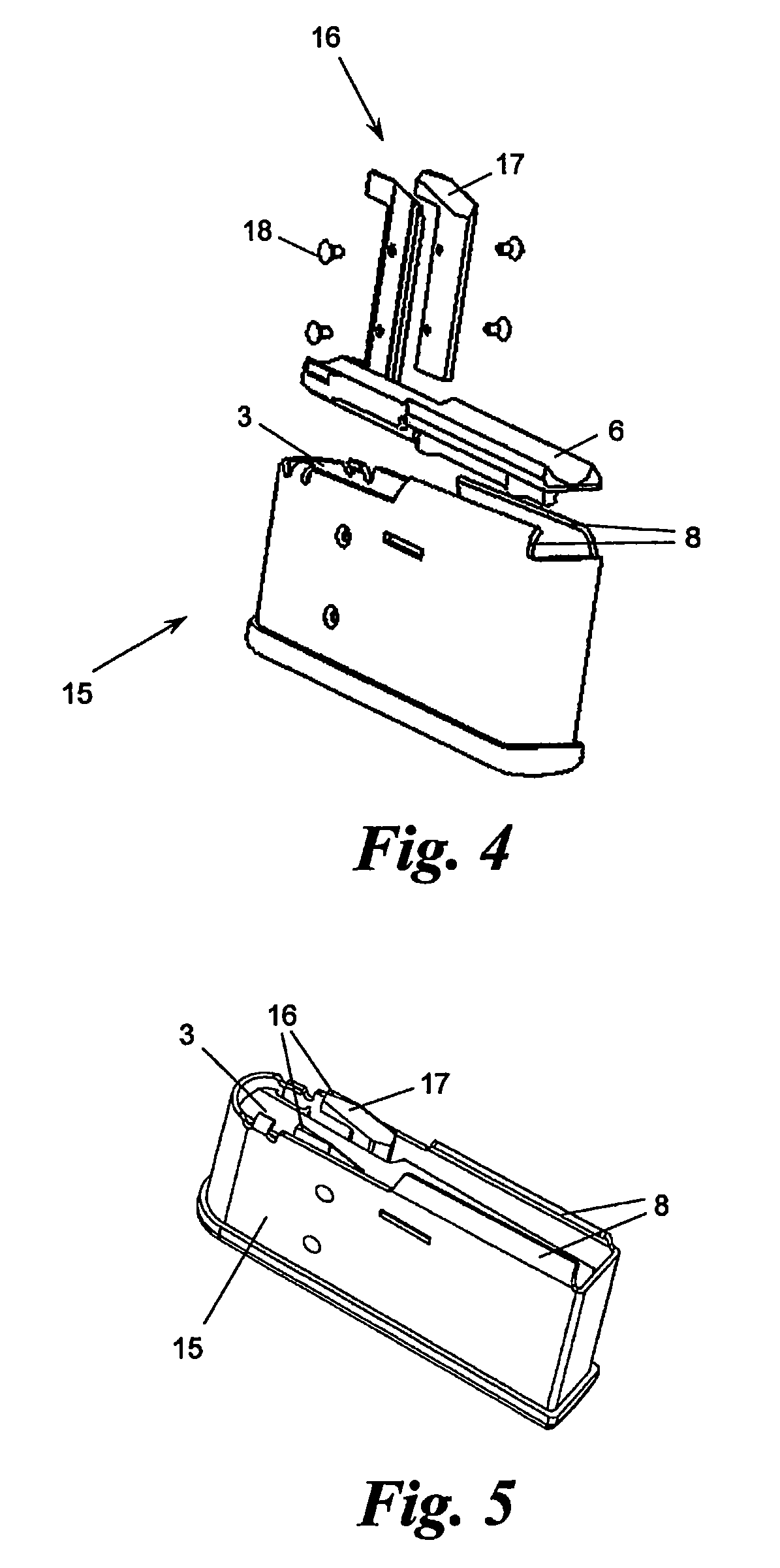
[0024]The rod magazine 15 illustrated in FIGS. 4 to 13 essentially corresponds to the rod magazine 1 shown in FIGS. 1 to 3, with the exception of its guide strips 16 and the details which will be described in the following text, with the same reference symbols being used in FIGS. 4 to 13 for the same parts as in FIGS. 1 to 3. References should therefore be made to the description of the corresponding parts of the rod magazine 1 for an explanation of these parts of the rod magazine 15.

[0025]The guide strips 16 of the rod magazine 15 are extended beyond the channel end 7, so that they project into the movement path, in front of the magazine lips 8, of the top cartridge 4. The end surfaces 17 of the guide strips 16 run at a slight angle, to be precise such that they project to a continuously greater extent as seen in the direction of the movement path the cartridge 4. The end surfaces 17 therefore result in the top cartridge 4 sliding and being slightly tilted upwards during the loadin...


PUM


Abstract

Rod magazine for a firearm, having a channel for holding cartridges in a stack, and having a feed for feeding the stack to a channel end which is clasped by magazine lips, which hold the top cartridge in the stack back in the channel direction, but allow its movement approximately transversely with respect to the channel direction beyond the rod magazine, with the channel being equipped with guide strips, which run in the channel direction, for the shoulders of the cartridges, and with the guide strips projecting beyond the channel end and into the movement path, which is located in front of the magazine lips, of the top cartridge.

Description

BACKGROUND OF THE INVENTION[0001]The present invention relates to a rod magazine for a firearm, having a channel for holding cartridges in a stack and having a feed for feeding the stack to a channel end which is overlapped by magazine lips which hold the top cartridge in the stack back in the channel direction, but allow it to move approximately transversely with respect to the channel direction beyond the rod magazine, with the channel being equipped with guide strips, which run in the channel direction, for the shoulders of the cartridges.[0002]FIGS. 1 to 3 show a rod magazine 1 such as this according to the prior art in the form of a perspective view (FIG. 1) and in two different operating positions, in the form of a section, in conjunction with a repeating rifle 2, a detail of which is illustrated (FIGS. 2, 3) . The rod magazine 1 has a channel 3 for holding cartridges 4, 4′ in a stack. Side guide strips 5 in the channel 3 act as a stop for the shoulders of the cartridges 4, 4′...

Claims


Application Information

Patent Timeline
Patent Type & Authority Patents(United States)
IPC IPC(8): F41A9/65
CPCF41A9/71F41A9/70
Inventor GRUBER, JOSEFKEFER, HUBERT
Owner STEYR MANNLICHER
Learn More