Heavy caliber firearm with enhanced recoil and control characteristics

a heavy-caliber, firearm technology, applied in the direction of weapons, breech mechanisms, weapons, etc., can solve the problems of safety, adverse effects on accuracy and ease of use, and varied side effects that prove detrimental both to accuracy and effectiveness

Inactive Publication Date: 2010-04-20
GAMMA RECH & TECH PATENTS
View PDF91 Cites 7 Cited by
  • Summary
  • Abstract
  • Description
  • Claims
  • Application Information

AI Technical Summary

Benefits of technology

[0022]The recoil control device's components can be advantageously prepared with comparatively large parts or large diameter spindles or rods, which simplifies manufacture. This advantage of the present invention greatly improves the reliability in service and the resistance to jamming by sand, mud, and other environmental contaminants and simplifies cleaning and dismantling of the firearm.
[0023]The mechanisms and aspects of the invention can be used to complement or improve existing or conventional firearms and can be combined with various arrangements, attachments, and combinations, including without limitation, internal release systems, loading systems, ejection systems, gas injection systems, recoil reduction systems, muzzle brakes, sighting systems, tripods, mounting systems, and firing mechanisms.
[0024]In one general aspect, the invention comprises an improved and novel recoil control device for use in a firearm, such as a semiautomatic or automatic firearm, in which, for example, a bolt head is configured to alternate between a forward position and a rearward position in response to the firing of one or more cartridges; and an inertia block is connected to the bolt head such that the bolt head imparts an impulse to the inertia block as it alternates between its forward position and its rearward position, the impulse having a component, or force distribution, or vectorial force component, lateral to the firing axis of the barrel of the firearm. The force transferred to the inertia block can be in any one of several directions and the inertia block can therefore traverse one of a variety of paths from the impulse imparted through the bolt head, including, but not limited to: a downward sloping, straight path toward the anterior of the firearm; a path comprising a rotation; a curved or curvi-linear path; a path extending outward from the barrel; a path moving inward toward the barrel; and a path crossing over the barrel. The path chosen relates to the design characteristics of the firearm desired.
[0025]Similarly, the inertia block or mass appropriate for a particular firearm relates to the design characteristics of the firearm. In one embodiment, the inertia block comprises a sloped or angled surface, or a leading sloped surface, that can be contacted by the bolt head to transmit the impulse from firing. In other embodiments, the inertia block comprises a part or parts that reciprocates between two or more positions and moves in response to the impulse from the bolt head. Multiple inertia blocks can also be used so that they move together in response to the bolt head. In another preferred embodiment, the recoil control device of the present invention can be incorporated into heavy caliber firearm and cannon mechanisms. For example, a heavy caliber rifle, such as a vehicle-mounted rifle or portable rifle of between .50 caliber and 155 mm, or even higher, can be produced with an inertia block to translate forces out of the axis of the barrel.
[0026]The transfer of the impulse of firing from the bolt head to the inertia block can be through direct contact between the two parts or through a simple or even a complex linkage. In one embodiment, one or more pin and rod assemblies are used. In another embodiment, a pin connected to the bolt head moves within a slot connected to the inertia block. In other embodiments, one or more reciprocating rods connect the bolt head to the inertia block.
[0027]For most firearms of the invention, the inertia block and bolt head are designed to automatically return to their resting or chambered position. A variety of mechanisms can be used to move the bolt head and / or inertia block in the return path. A preferred embodiment employs a spring operably connected to or contacting the inertia block, which can be referred to as the return spring. A variety of spring types can be adapted for this purpose. Alternative return or recovery mechanisms can be designed by one of skill in the art.

Problems solved by technology

For automatic weapons, the rapid firing of successive cartridges induces various side effects that prove detrimental both to accuracy and effectiveness.
Throughout these improvements, a main issue was safety.
A common but unsatisfactory feature among all theses mechanisms is that they do not prevent the undesirable side effects during automatic firing, which accounts for the adverse effects on accuracy and ease of use.
Thus, the mechanisms found on current firearms, although reliable and widely employed, nevertheless suffer from a number of deficiencies.
For example, some mechanisms increase the length of the housing of the breech, resulting in interior clutter and increased weight.
The amplitude of recoil is relatively critical due to its effect on accuracy, and the existing mechanisms fail to provide a satisfactory or optimum reduction in recoil, which permits the resulting upward movement of the barrel.
Heavy caliber firearms and cannons experience the same upward forces upon firing, which often results in heavy strains on the mounting or emplacement apparatus.

Method used


Image

  • Heavy caliber firearm with enhanced recoil and control characteristics
  • Heavy caliber firearm with enhanced recoil and control characteristics
  • Heavy caliber firearm with enhanced recoil and control characteristics

Examples


Embodiment Construction

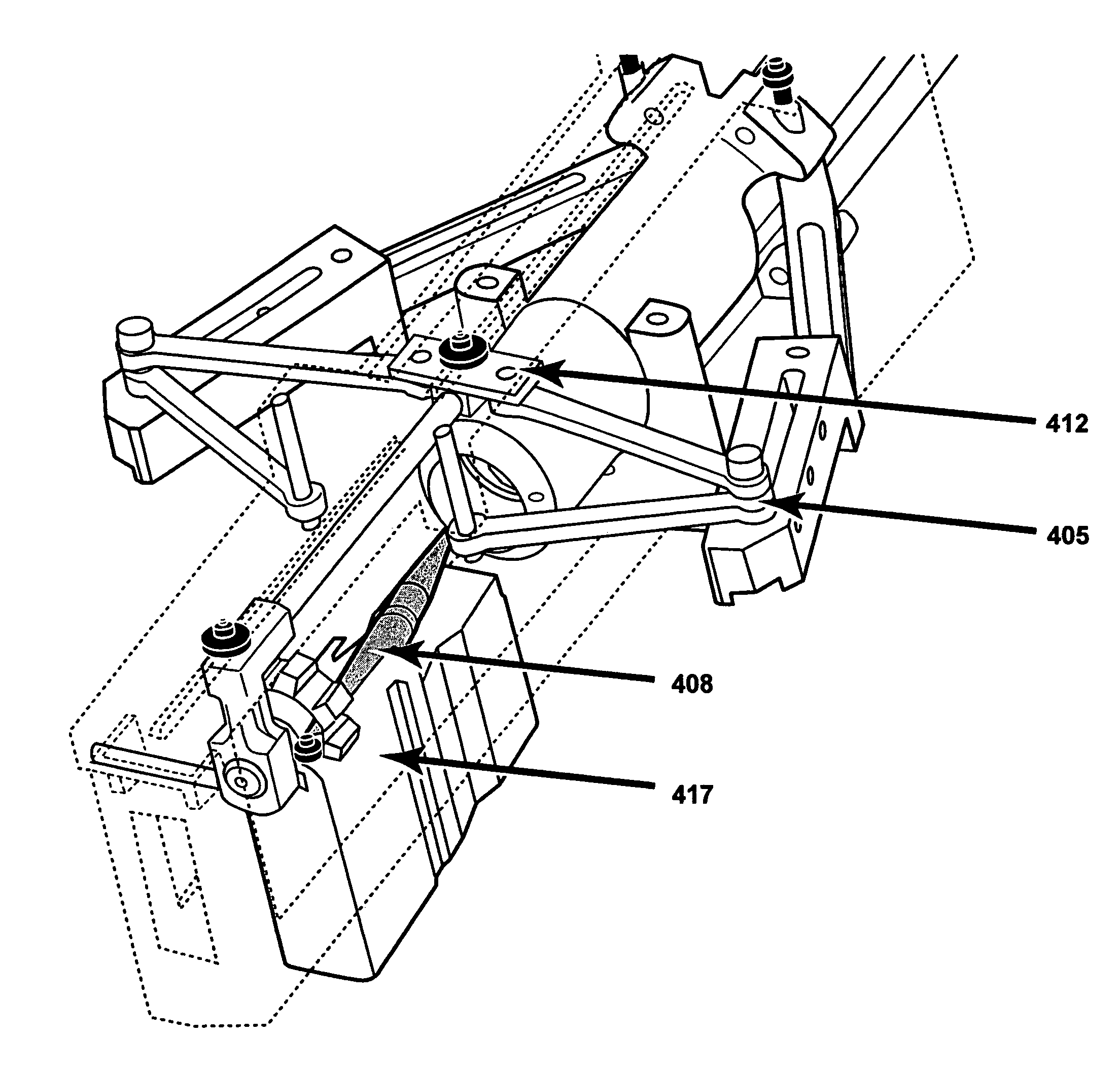
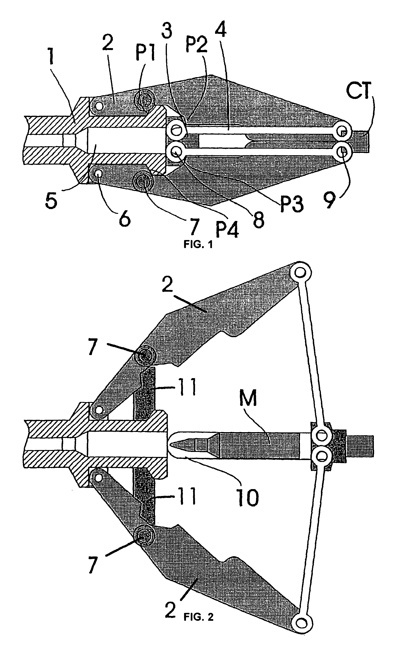
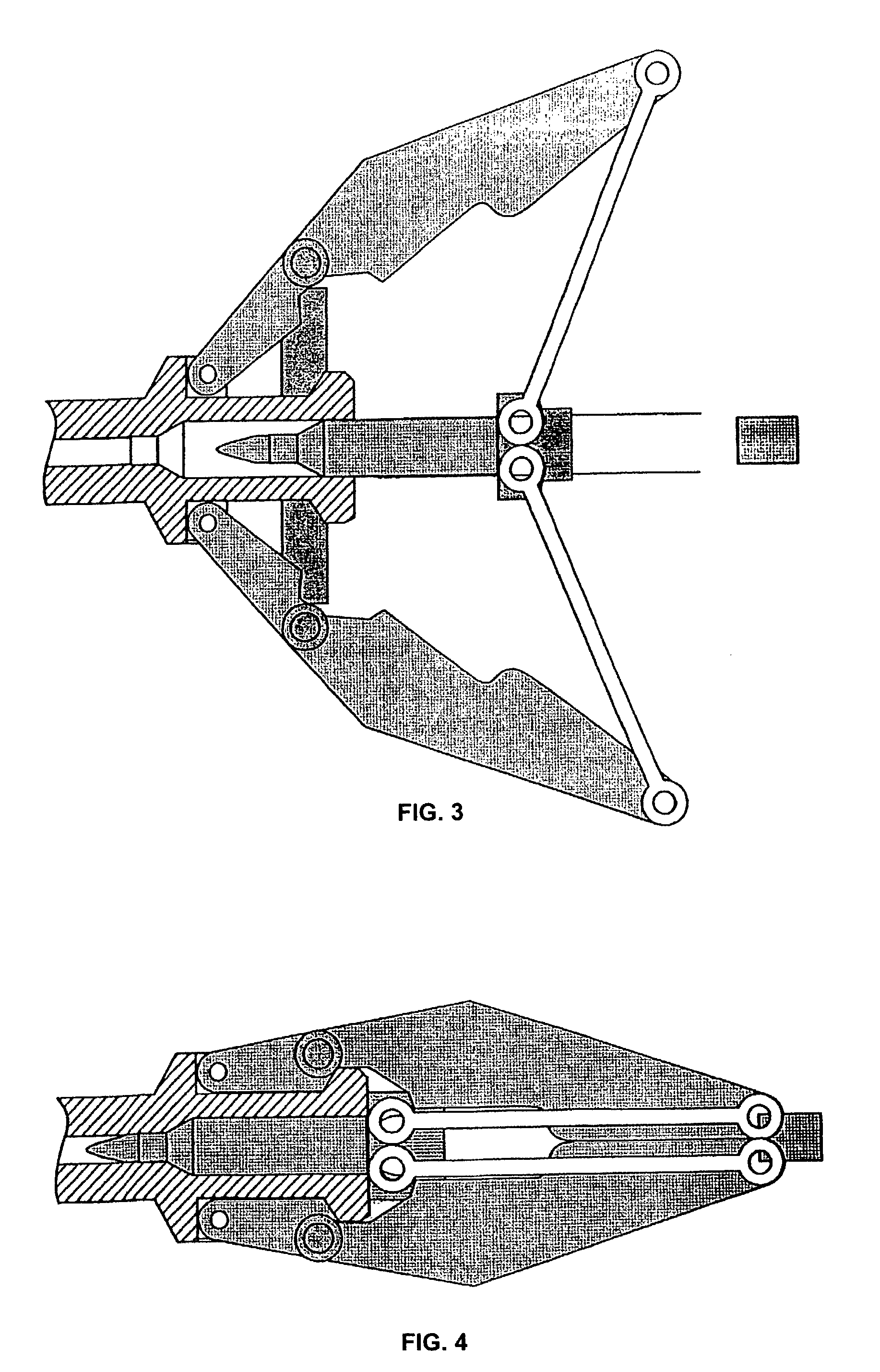
[0071]Whether for smaller caliber handguns or rifles, in other words pistols, machine pistols and assault rifles, or for the preferred embodiments of heavy caliber rifles, machine guns, or cannons, the present invention advantageously reduces the consequences of recoil and / or eliminates, for all practical purposes, the weapon's reactive jerking and permits a more compact and lighter weapon for a given caliber ammunition.

[0072]Where heavy firearms are concerned, for example, machine guns and cannons, notably machine guns for land, water craft, or airborne platforms, the present invention enables a lighter frame for the weapon and a more compact and therefore more stowable or containable weapon. This allows moveable weapon systems to store more ammunition per sortie. Further, this invention enables a simplified construction for the base by diminishing the recoil tendency and dampening the stress acting upon the platform as a whole. This is especially advantageous when composite materi...


PUM


Abstract

The invention comprises an improved recoil control device comprising a bolt head and an inertia block for use in a variety of firearms. In one embodiment, the bolt head and inertia block are articulated so that the displacement of the bolt head results in a force component outside the firing axis of the barrel of the firearm. The device can be incorporated into firearms of a variety of sizes and configurations to produce recoil reduction and / or weight reduction advantages.

Description

RELATED APPLICATIONS[0001]This application claims priority to U.S. Provisional Application No. 60 / 459,969, filed Apr. 4, 2003, which is incorporated by reference in its entirety. This application also claims priority to Swiss Application Nos. 0975 / 02, filed Jun. 7, 2002, 1343 / 02, filed Jul. 31, 2002, and 0679 / 03, filed Apr. 15, 2003, which are incorporated by reference in their entirety.FIELD OF INVENTION[0002]This invention relates to small and heavy caliber firearms and cannons as well as to improved methods and devices for reducing the consequences of recoil and improving performance in firearms and cannons. In a particular embodiment, the device relates to the control or management of the recoil forces for semiautomatic or automatic firearms.BACKGROUND FOR AND INTRODUCTION TO THE INVENTION[0003]Historically, firearms were built to be loaded and fired mechanically. Even today, many heavy caliber guns and cannons are loaded by hand or individually loaded. For automatic weapons, th...

Claims


Application Information

Patent Timeline
Patent Type & Authority Patents(United States)
IPC IPC(8): F41A3/56F41A3/84F41A5/12
CPCF41A3/56F41A5/12F41A3/84
Inventor JEBSEN, JAN HENRIKKERBRAT, RENAUD
Owner GAMMA RECH & TECH PATENTS
Why Eureka
Try Eureka