
Discharge amount measurement method, pattern formation method, device, electro-optical device, and electronic instrument

a technology of discharge amount and measurement method, which is applied in the direction of coatings, printing, other printing devices, etc., can solve the problems of difficult to minimize the fluctuation of droplet discharge amount, excessive or inadequate color of light that passes through the color filter, and significant color variation, etc., to achieve stable electro-optical characteristics

Active Publication Date: 2010-04-20
KATEEVA
View PDF6 Cites 23 Cited by
  • Summary
  • Abstract
  • Description
  • Claims
  • Application Information

AI Technical Summary

Benefits of technology

[0013]In accordance with another aspect of the present invention, a weight is measured as the discharge amount of the discharged liquid in the measurement step. The quantity of the discharged liquid is thereby measured according to the weight thereof. The discharged droplets tend not to assume a consistent shape after landing on the workpiece, and the discharge amount of the liquid can be measured more easily than by a volume measurement. Devices for converting the value of a measured weight into an electric current are also widely used, and the discharge amount can be measured with good precision by converting the weight into an electric current and measuring the quantity of electric current.
[0015]It is also preferred that the measurement discharge data comprise all-nozzle non-discharge information in which none of the nozzles discharge the liquid, and that the measurement discharge data be used in a state in which a portion of the continuous all-nozzle non-discharge information is deleted when the all-nozzle non-discharge information is continuous. Since the measurement discharge data are used in a state in which a portion of the continuous all-nozzle non-discharge information is deleted, the amount of time needed to discharge droplets for measurement can be reduced.
[0017]When a liquid is discharged from a plurality of nozzles to form a drawing pattern, the number or distribution of nozzles that are used simultaneously varies, and this variation also affects the discharge amount of the discharged droplets. According to this method, measurement discharge data are used that include first measurement discharge data that have information about continuously non-discharging nozzles among the plurality of nozzles, and second measurement discharge data that have information about nozzles that change from non-discharging nozzles to nozzles that continuously discharge liquid. As a result, droplets are discharged by a prescribed number of discharges from all of the nozzles, and the discharge amount can be more accurately calculated.
[0021]It is preferred that the functional fluid be discharged into a pattern using a plurality of droplet discharge heads in the drawing step, that the functional fluid be discharged for each of the plurality of droplet discharge heads in the measurement discharge step, that the discharge amount of the functional fluid discharged for each of the plurality of droplet discharge heads be measured in the measurement step, and that adjustment be performed in the adjustment step so that a difference in the average discharge amount among the plurality of droplet discharge heads is reduced. It is thereby possible to form a drawing pattern that has little variation in thickness due to a difference in the average discharge amount among the plurality of droplet discharge heads.
[0025]The device in accordance with another aspect of the present invention has a drawing pattern that is composed of a functional material, and the device is characterized in that the drawing pattern is created using the pattern formation method according to the aforementioned aspects of the present invention. In this configuration, a pattern formation method is used that is capable of forming a drawing pattern having little variation in film thickness caused by fluctuation of the droplet discharge amount. It is therefore possible to provide a device that has stable characteristics. For example, when the device is a color filter, it is possible to obtain the desired optical characteristics in a color layer. The characteristics include transmittance, color, and saturation. When the device is an organic EL (electroluminescence) element, the desired quantity of functional fluid can be applied to form a positive hole implantation layer, a light-emitting layer, or an electron implantation layer, and an element can therefore be formed whose layers have the appropriate thickness. As a result, an organic EL element can be provided that emits light with high efficiency.
[0027]The electronic instrument in accordance with another aspect of the present invention is characterized in comprising the electro-optical device according to the aforementioned aspect of the present invention. A high-quality electronic instrument that has stable electro-optical characteristics can thereby be obtained.

Problems solved by technology

For example, when the quantity of discharged droplets that include a colorant material is inappropriate in a method for forming a color filter, the light that passes through the color filter is excessively or inadequately colored, and a color filter is obtained that has inconsistent quality and significant variation in color.
However, the above mentioned reference does not describe the pattern and discharge timing at which droplets are discharged onto the workpiece.
Specifically, it is difficult to minimize fluctuations in the droplet discharge amount that are caused by the drawing pattern in which droplets are discharged onto the workpiece.

Method used


Image

  • Discharge amount measurement method, pattern formation method, device, electro-optical device, and electronic instrument
  • Discharge amount measurement method, pattern formation method, device, electro-optical device, and electronic instrument
  • Discharge amount measurement method, pattern formation method, device, electro-optical device, and electronic instrument

Examples


first embodiment

[0073]A color filter and a method for manufacturing the same will next be described as an embodiment of the device of the present invention. FIG. 6 is a schematic plan view showing a color filter.

[0074]As shown in FIG. 6, the color filter of the present embodiment has a divider portion (bank) 15 for partitioning a plurality of drawing regions A into a matrix on the substrate W, and three colors (RGB) of color layers formed within the partitioned drawing regions A. This color filter has a so-called striped system in which color layers of the same color are arranged linearly in the same direction.

[0075]The divider portion 15 is formed using a publicly known material and method. In an example of this method, a photosensitive resin material is applied on the substrate W, and the divider portion 15 is formed by a photolithography technique. Light that passes through the substrate W is preferably blocked by the divider portion 15, and a divider portion 15 composed of a photosensitive resi...

second embodiment

[0099]A second embodiment of the discharge amount measurement method of the present invention will next be described according to FIG. 10. FIG. 10 is a block diagram showing the electrical control system by which the discharge amount is measured.

[0100]As shown in FIG. 10, the droplet discharge device 20 is provided with a device 77 for generating a theoretical position value. All other aspects are the same as in the block diagram of FIG. 5 that shows the electrical control system of the droplet discharge device of the first embodiment.

[0101]In the first embodiment described above, the main scanning control computation unit 70 of the CPU 54 transmits stage movement position data to the main scanning drive device 58, and the main scanning drive device 58 drives the stage 23. The main scanning position detection device 24 transmits data relating to the position of the stage 23 to the nozzle discharge control computation unit 72 of the CPU 54. The nozzle discharge control computation un...

third embodiment

[0106]A third embodiment of the discharge amount measurement method of the present invention will next be described according to FIGS. 11 through 14. FIG. 11 is a schematic plan view showing a droplet discharge head in the third embodiment; FIGS. 12A, 12B, 13A and 13B are schematic views showing the method by which liquid is discharged in the third embodiment; and FIG. 14 is a schematic view showing the measurement discharge data.

[0107]As shown in FIG. 11, the droplet discharge head 40 in the present embodiment is provided with two nozzle rows 42A, 42B that comprise a plurality (180) of nozzles 42. A plurality of nozzles 42 is arranged at a substantially equal nozzle pitch P in each nozzle row 42A, 42B, and the nozzle rows 42A, 42B are arranged so as to be offset from each other by one half nozzle pitch.

[0108]The ten nozzles 42 positioned on the ends of the nozzle rows 42A, 42B are not used, and there are 160 effective nozzles in each row.

[0109]In this case, the number and positioni...


PUM


Abstract

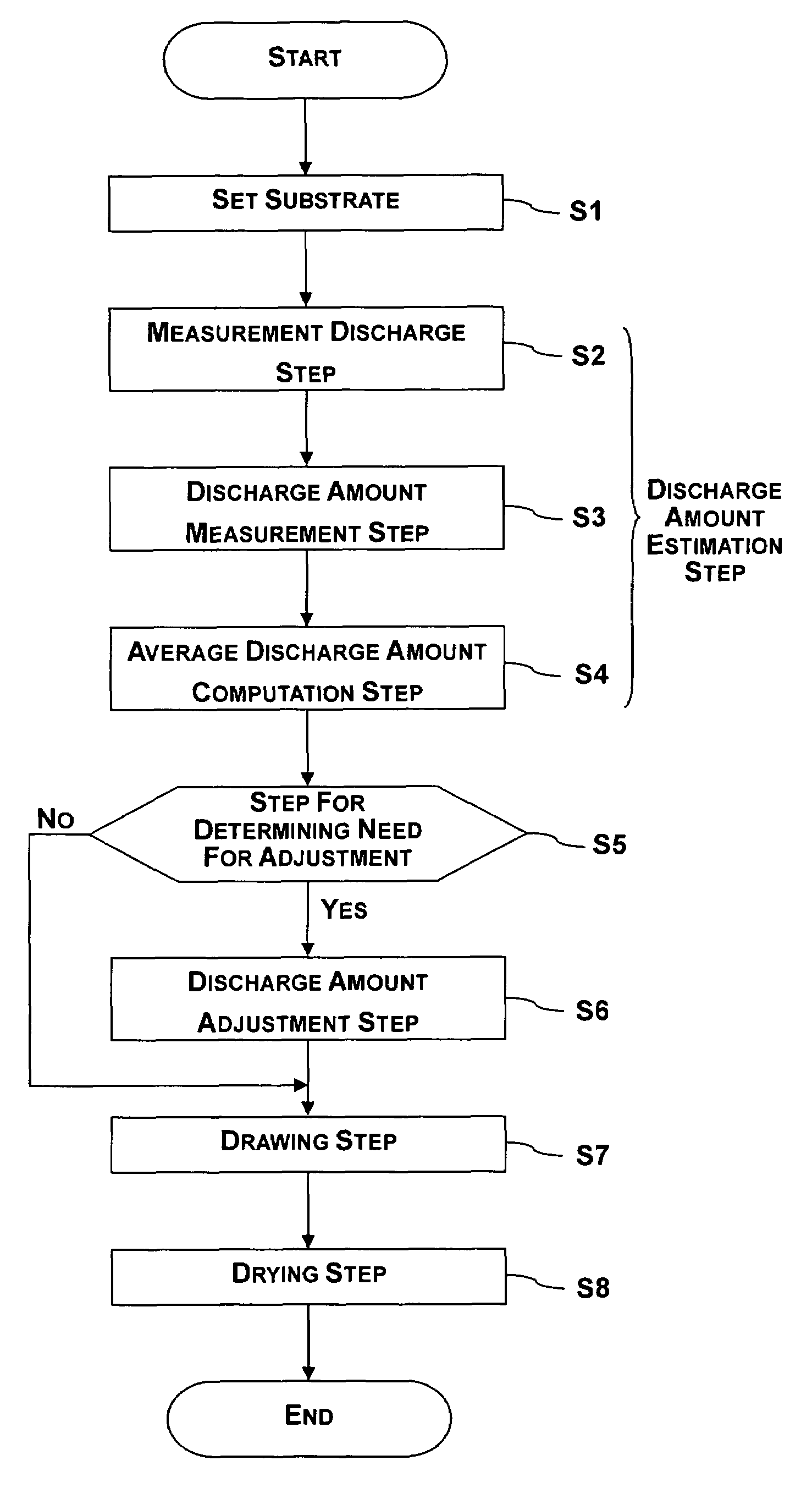
A discharge amount measurement method is configured to measure a discharge amount of a liquid discharged from at least one nozzle of a droplet discharge head. The discharge amount measurement method includes discharging the liquid as a droplet from the at least one nozzle of the droplet discharge head by a number of discharges that is set to obtain a measurable quantity by driving the droplet discharge head based on measurement discharge data that is substantially identical to data used when a drawing pattern is formed by discharging the liquid from the at least one nozzle of the droplet discharge head, measuring the discharge amount of the liquid discharged from the at least one nozzle of the droplet discharge head, and calculating an average discharge amount based on the discharge amount and the number of discharges.

Description

CROSS-REFERENCE TO RELATED APPLICATIONS[0001]This application claims priority to Japanese Patent Application Nos. 2005-327923 filed on Nov. 11, 2005 and 2006-252482 filed on Sep. 19, 2006. The entire disclosures of Japanese Patent Application Nos. 2005-327923 and 2006-252482 are hereby incorporated herein by reference.BACKGROUND OF THE INVENTION[0002]1. Field of the Invention[0003]The present invention relates to a discharge amount measurement method, to a pattern formation method, to a device, to an electro-optical device, and to an electronic instrument in a droplet discharge method.[0004]2. Background Information[0005]A method has been proposed for forming a color filter in a liquid crystal display device or a light-emitting layer in an organic EL display device, for example, by utilizing an inkjet system (droplet discharge method) that is used in an inkjet printer.[0006]In this type of droplet discharge method, the quantity of droplets discharged from the droplet discharge head ...

Claims


Application Information

Patent Timeline
Patent Type & Authority Patents(United States)
IPC IPC(8): B41J29/393
CPCB41J2/17566B41J2002/17569B05C11/02B05C21/00
Inventor KATO, TSUYOSHI
Owner KATEEVA
Learn More