LIDAR system

a technology of sliding system and camera, applied in the field of sliding system, can solve the problems of additional system (camera-to-lidar) alignment and calibration, possible parallax errors, and system complexity and cos

Active Publication Date: 2010-04-20
LEICA GEOSYSTEMS AG
View PDF6 Cites 98 Cited by
  • Summary
  • Abstract
  • Description
  • Claims
  • Application Information

AI Technical Summary

Problems solved by technology

As discussed above, a second camera is required, adding to system complexity and costs, and requiring additional system (camera-to-LIDAR) alignments and calibrations.
The parallel systems also result in registration errors (physical and software) and possible parallax errors, and often operate on the basis of different color and LIDAR resolutions (pixel sizes, spot sizes).
In brief, the result is a dual optical system that is not only complex, but also suffers from generally imperfect registration and mismatched optical resolutions.

Method used


Image

  • LIDAR system
  • LIDAR system
  • LIDAR system

Examples


Embodiment Construction

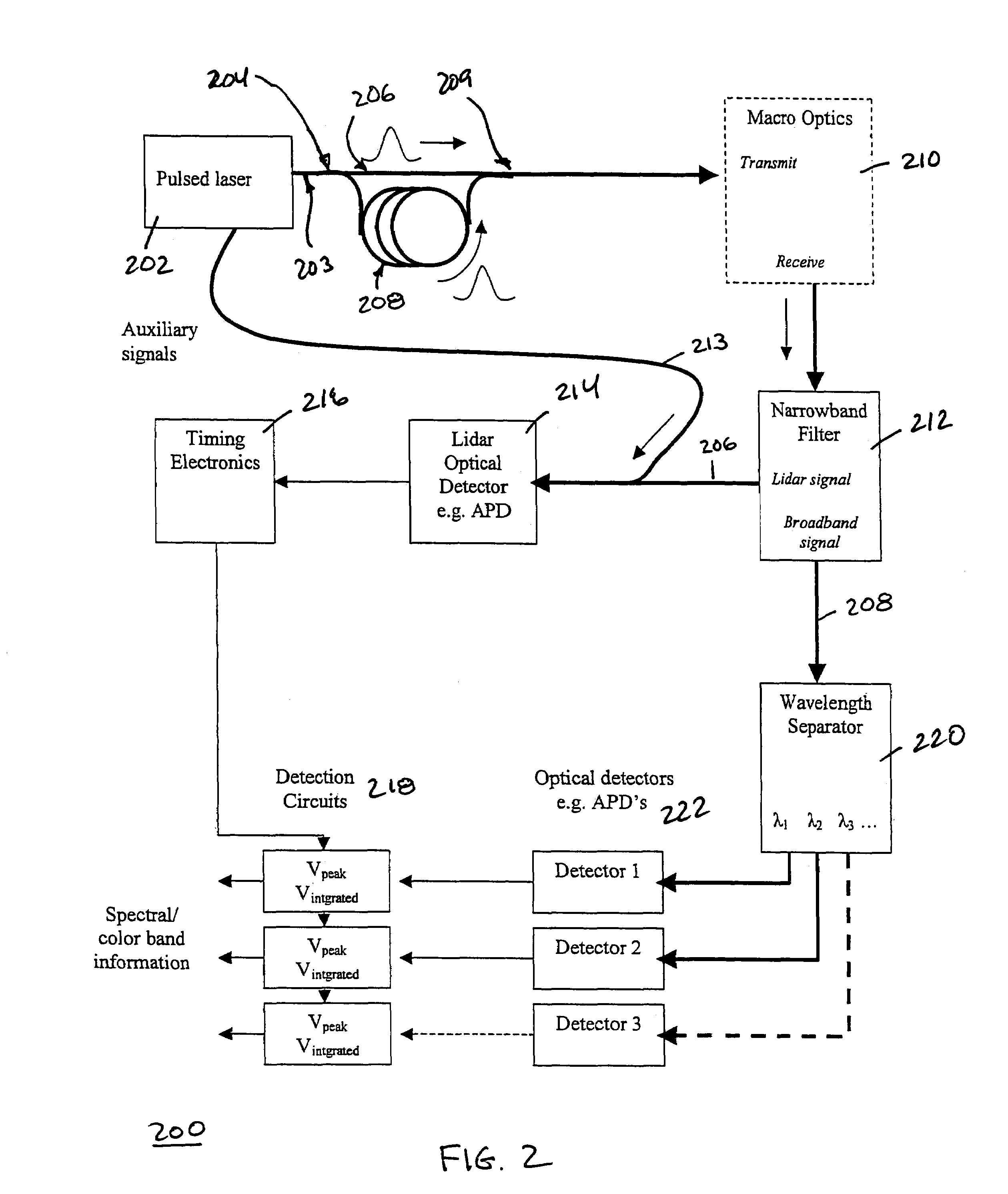
[0018]FIG. 2 shows an embodiment of a full color LIDAR system 200 in accordance with the present invention.

[0019]In the FIG. 2 system 200, a pulsed laser 202 provides a laser pulse that is propagated down an optical path, preferably a single mode optical path 203, and divided by a 2× fiber optic splitter 204 into two paths. The first path 206, a direct monochromatic “LIDAR” laser pulse, is coupled directly to transmitter macro-optics 210, e.g. beam collimation optics. The second path 208, the “illumination” path, is split off and delayed through a comparatively long non-linear fiber that wavelength-broadens the output to form a super-continuum or delayed wavelength-broadened “white” illumination laser pulse. The first LIDAR optical path 206 and the second illumination optical path 208 are recombined by a second fiber optic coupler-splitter 209 and launched out of a common fiber exit of the coupler-splitter 209 towards the macro-optics 210. The monochromatic LIDAR pulse 206 forms the...


PUM


Abstract

Methods for using spectrally separated light pulses to collect more LIDAR information are presented. In one embodiment, a monochromatic pulse is transmitted to collect range information and a white pulse is transmitted a short time afterwards to collect spectral responsivity information or color of the target. In another embodiment, the white light pulse is used to collect both range and spectral responsivity information of the target. In another embodiment, the spectral separated laser is spatially spread in order to collect range information over more than one point at a time.

Description

PRIORITY CLAIM[0001]This application claims the benefit of U.S. Provisional Application No. 60 / 846,617, filed on Sep. 22, 2006, by Gregory C. Walsh and titled “Full Color LIDAR System.” Provisional Application No. 60 / 846,617 is hereby incorporated by reference herein in its entirety.BACKGROUND OF THE INVENTION[0002]The acquisition of data and subsequent generation of computer models for real-world objects is of interest in many industries and for many applications including architecture, physical plant design, entertainment applications (e.g., in movies and games), surveying, manufacturing quality control, medical imaging, and construction, as well as in cartography and geography applications. In order to obtain accurate 3D models of an object, as well as the area in which that object exists in the real world, it is necessary to take accurate measurements or samplings of surfaces that make up the object and any elements of the surrounding area. Historically, this sampling was carrie...

Claims


Application Information

Patent Timeline
Patent Type & Authority Patents(United States)
IPC IPC(8): G01C3/08G01S7/4865G01S17/10G01S17/87G01S17/89
CPCG01S7/4818G01S7/483G01C3/08G01S17/89G01S17/87G01S7/497G01S7/4865G01S17/10
Inventor WALSH, GREGORY C.AINDOW, ALAN
Owner LEICA GEOSYSTEMS AG
Why Eureka
Try Eureka