Cooling structure for rackmount-type control device and rack-type storage control device

a control device and rackmount technology, applied in the direction of instruments, furniture parts, electrical apparatus casings/cabinets/drawers, etc., can solve the problems of reducing the surface area that can be used for electrical connections of the total surface area of the connection substrate, and difficulty in uniform air cooling of the respective parts of the cooling targ

Inactive Publication Date: 2010-04-20
HITACHI LTD
View PDF13 Cites 44 Cited by
  • Summary
  • Abstract
  • Description
  • Claims
  • Application Information

AI Technical Summary

Benefits of technology

[0010]Therefore, an object of the present invention is to provide a cooling structure of a rackmount-type control device and a rack-type storage control device that makes it possible to improve the cooling efficiency. A further object of the present invention is to provide a cooling structure of a rackmount-type control device and a rack-type storage control device that permit efficient cooling of the interior of an enclosure in which control substrate groups and power-related devices are each densely mounted in front of and behind the connection substrate. Further objects of the present invention will become evident from the description of the embodiments that will follow subsequently.

Problems solved by technology

In cases where the interior of the enclosure is air-cooled by means of a large-scale cooling fan device, it is difficult to uniformly air-cool the respective parts of the cooling target (which are the controller, disk drives, and power-related devices).
In order to adequately cool the respective parts of the cooling target, a stronger cooling fan must be provided, which results in an increase in fabrication costs and electricity charges, and so forth.
However, a rack-type storage control device does not comprise a central cooling passage of this kind.
Hence, the surface area that can be used for electrical connections of the total surface area of the connection substrate is reduced and it is therefore difficult to more densely mount a greater number of substrates and devices.

Method used


Image

  • Cooling structure for rackmount-type control device and rack-type storage control device
  • Cooling structure for rackmount-type control device and rack-type storage control device
  • Cooling structure for rackmount-type control device and rack-type storage control device

Examples


first embodiment

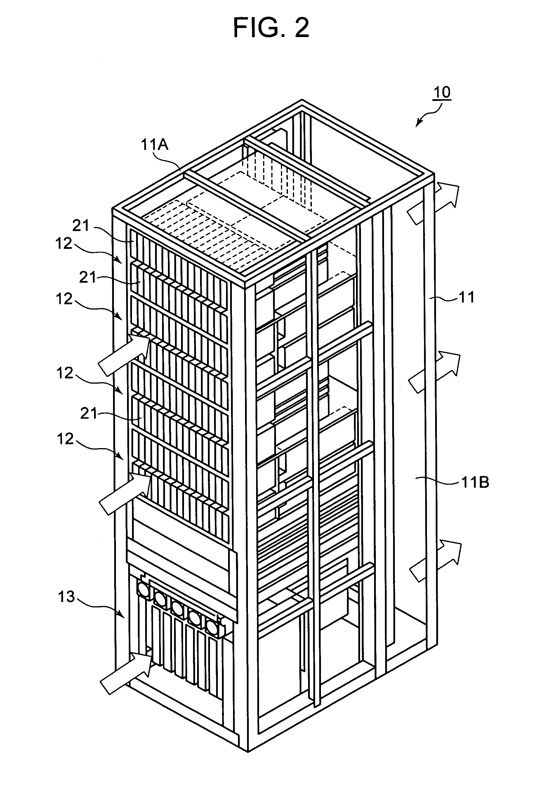
[0079]FIG. 2 is a perspective view showing the external constitution of a rack-type storage control device 10. The storage control device 10 comprises a rack 11, a plurality of hard disk boxes 12 which are attached detachably to the rack 11, and one controller 13 that is attached detachably to the bottom of the rack 11, for example.

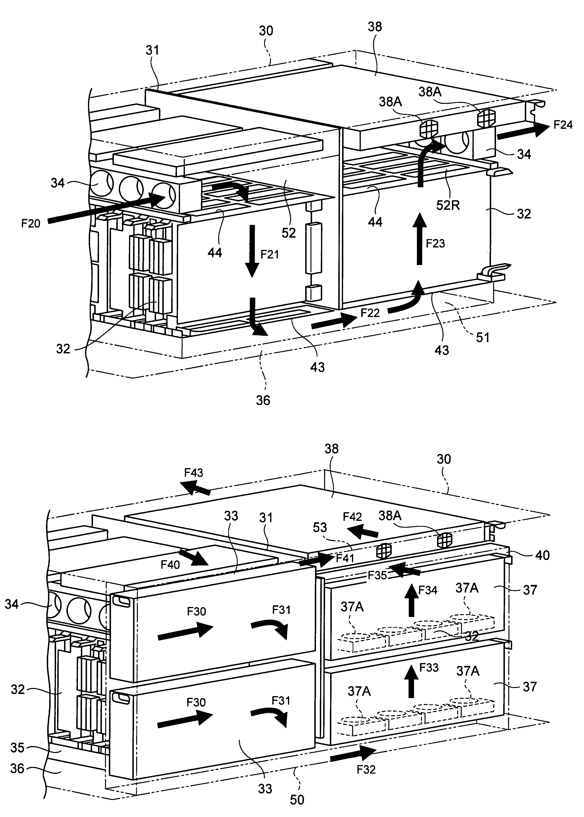
[0080]The controller 13 corresponds to the controller 1 in FIG. 1. As will be described subsequently, the controller 13 is provided with logic substrates 32, battery devices 33, and power supply devices 37 for constituting two clusters, where the right half when the controller 13 is viewed from the front constitutes one cluster and the left half constitutes the other cluster. The respective clusters each comprise a redundant configuration. Therefore, two each of the battery device 33 and power supply devices 37 are prepared for each cluster.

[0081]The rack 11 comprises a housing section 11A and a rear space section 11B that is provided at the rear side of ...


PUM


Abstract

According to the storage control device of the present invention, individual cooling passages are formed for each region in the enclosure and the respective cooling passages are formed bent so as to bypass the connection substrate. As a result, the interior of the enclosure is cooled efficiently. The interior of the enclosure is divided in the front-rear direction by the connection substrate. Logic substrates and battery devices are provided on the front side of the connection substrate and logic substrates and power supply devices are provided on the rear side of the connection substrate. The battery devices and power supply devices located on the left and right sides of the enclosure are each cooled by means of individual cooling passages. The logic substrates are cooled by means of different cooling passages.

Description

CROSS-REFERENCE TO RELATED APPLICATIONS[0001]This application relates to and claims priority from Japanese Patent Application No. 2007-220647 filed on Aug. 28, 2007, the entire disclosure of which is incorporated herein by reference.BACKGROUND OF THE INVENTION[0002]1. Field of the Invention[0003]The present invention relates to a cooling structure for a rackmount-type control device and a rack-type storage control device.[0004]2. Description of the Related Art[0005]A storage control device comprises a storage section in which a multiplicity of disk drives are connected in the form of an array and provides a host computer (‘host’ hereinbelow) such as a server with logical storage regions (logical volumes). In order to increase reliability and so forth, the storage control device provides a host with a RAID (Redundant Array of Independent Disks)-based redundant storage region.[0006]A controller, a multiplicity of disk drives and power-related devices, which are housed in the enclosure...

Claims


Application Information

Patent Timeline
Patent Type & Authority Patents(United States)
IPC IPC(8): H05K7/00G06F1/20H05K5/00
CPCH05K7/20727G11B33/142
Inventor TANAKA, SHIGEAKIKASAHARA, YOSHIKATSU
Owner HITACHI LTD
Why Eureka
Try Eureka