Cleaning device

a cleaning device and cleaning technology, applied in the direction of optics, instruments, electrographic processes, etc., can solve the problems of toner image deterioration, and high risk of leakage, and achieve the effect of suppressing image jitter or nois

Active Publication Date: 2010-04-20
KYOCERA DOCUMENT SOLUTIONS INC
View PDF6 Cites 11 Cited by
  • Summary
  • Abstract
  • Description
  • Claims
  • Application Information

AI Technical Summary

Benefits of technology

[0009]Another object of the invention is to provide a cleaning device that enables to suppress image jitter or noise resulting from jitter of a photosensitive drum.

Problems solved by technology

Amorphous silicon to be used as a material for the amorphous silicon photosensitive drum has a relatively large hardness and a long useful life, but has a disadvantage that an electric charge is likely to leak during a long-term use.
Accordingly, there is a likelihood that a toner image may be deteriorated in use of the amorphous silicon photosensitive drum.
In the above arrangement, however, there is a likelihood that jitter of a photosensitive drum may cause image jitter or noise.
In other words, in the arrangement of driving the spiral roller by the gear of the cleaning roller, the driving force of the cleaning roller may fluctuate, which may cause jitter of the photosensitive drum, thereby resulting in image jitter or noise.

Method used


Image

  • Cleaning device
  • Cleaning device
  • Cleaning device

Examples


Embodiment Construction

[0019]In the following, a cleaning device embodying the invention is described in detail referring to the drawings.

[0020]Before the cleaning device according to the embodiment is described, the entire construction of a tandem color printer (hereinafter, simply called as a “printer”) 2, as an example of an image forming apparatus provided with the cleaning device, is described referring to FIG. 6.

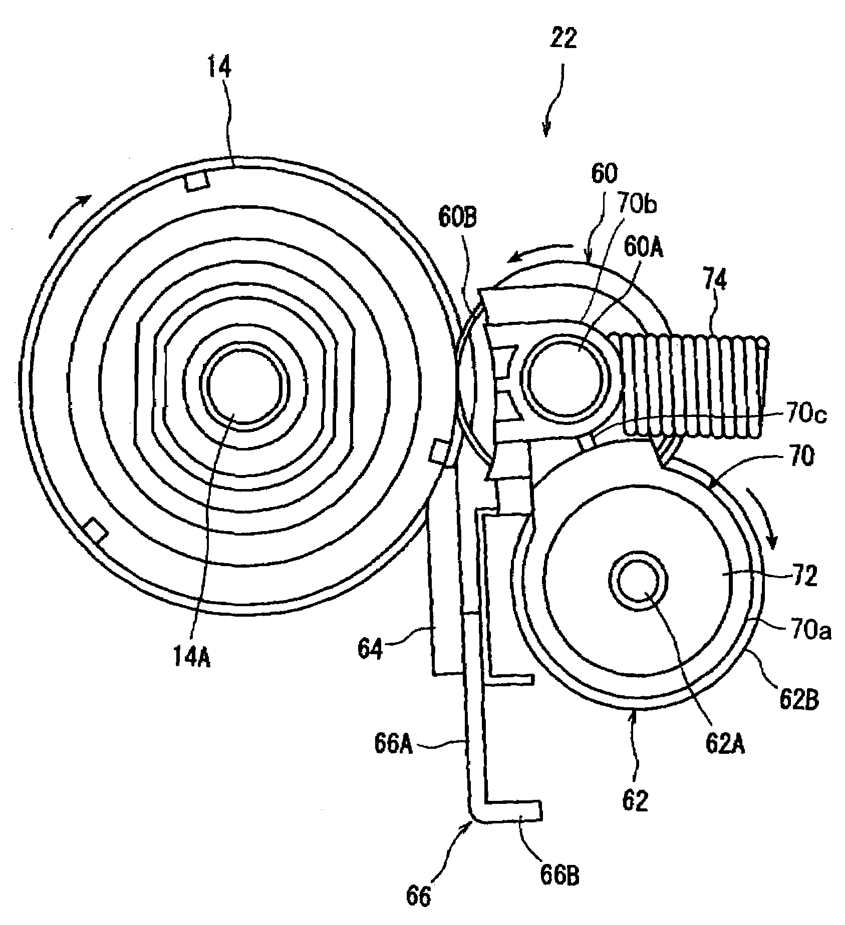
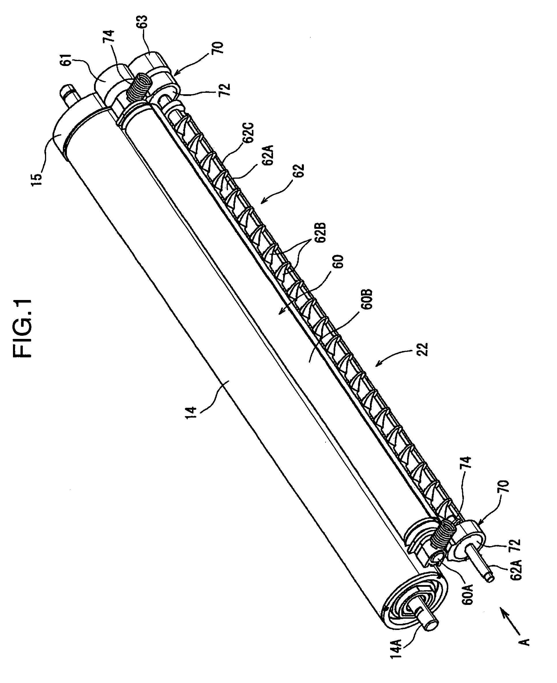
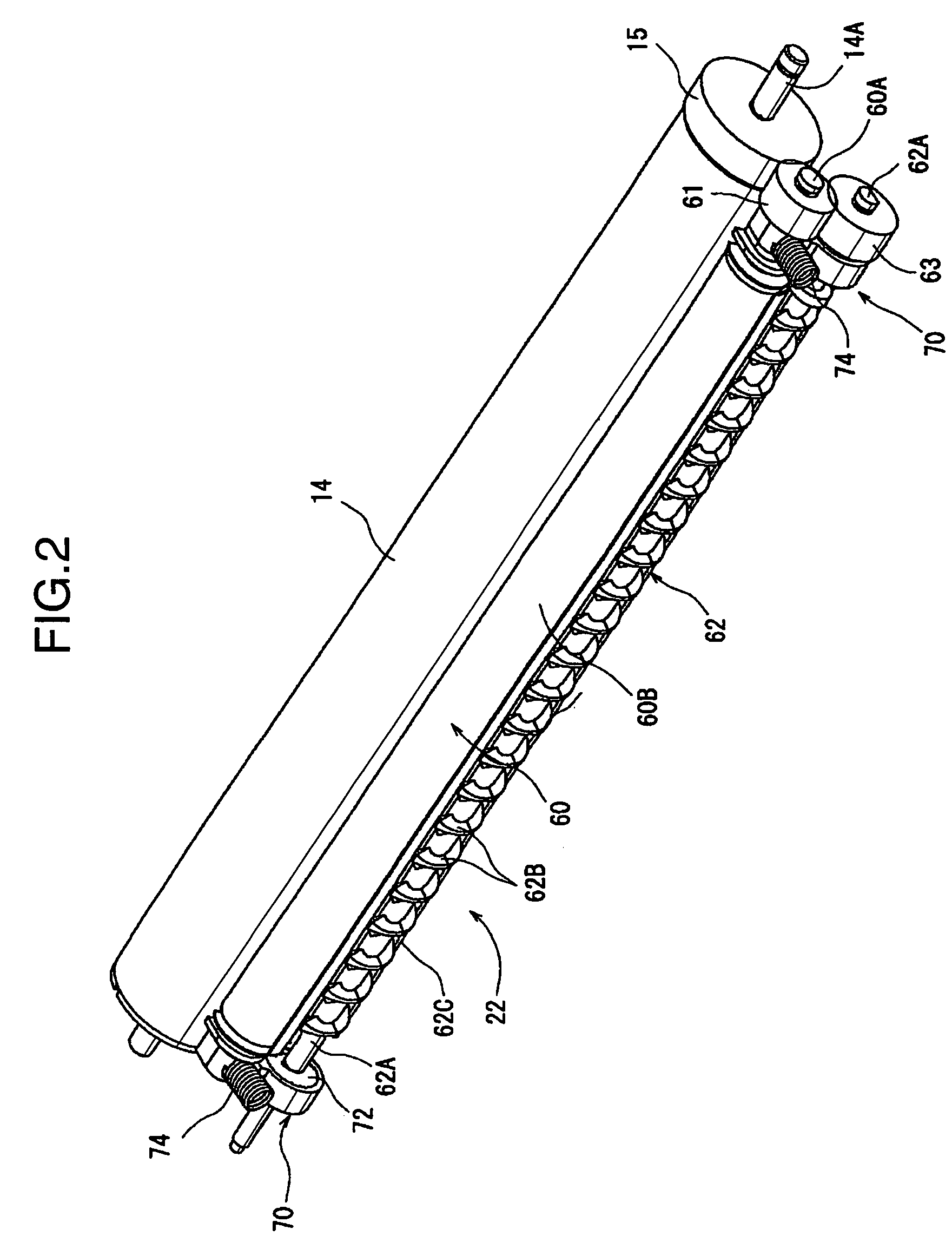
[0021]The printer 2 has a main body 4 as a substantially rectangular parallelepiped image forming apparatus main body. A magenta processing unit 6M, a cyan processing unit 8C, a yellow processing unit 10Y, and a black processing unit 12BK are arranged in the printer main body 4. The processing units 6M, 8C, 10Y, and 12BK are arranged in this order from upstream in a sheet transport direction. Each of the processing units 6M, 8C, 10Y, and 12BK includes imaging elements such as a photosensitive drum 14, a charger 16, a developer 18, a primary transfer roller 20, and a cleaning device 22. An am...


PUM


Abstract

A cleaning device includes: a first shaft; a cleaning roller which is operable to come into contact with a surface of a photosensitive drum, and is integrally rotated with the first shaft; a pressing member for pressing the cleaning roller against the surface of the photosensitive drum; a second shaft; a spiral roller which is integrally rotated with the second shaft, and is operative to collect toner residues from the surface of the photosensitive drum; a driving force transmitting mechanism for transmitting a driving force of the photosensitive drum to the first shaft and the second shaft; and a pair of arm members which are pivotally interlocked with the second shaft, and are pivotally interlocked with the first shaft. The cleaning device allows for suppressing image jitter or noise resulting from jitter of the photosensitive drum.

Description

BACKGROUND OF THE INVENTION[0001]1. Field of the Invention[0002]The present invention relates to a cleaning device for use in an image forming apparatus such as an electrostatic copier, a laser printer, and a facsimile machine, and more particularly to a cleaning device for use in an image forming apparatus provided with an a-Si (amorphous silicon) photosensitive drum.[0003]2. Description of the Related Art[0004]There is known an mage forming apparatus e.g. a printer provided with an amorphous silicon photosensitive drum. Amorphous silicon to be used as a material for the amorphous silicon photosensitive drum has a relatively large hardness and a long useful life, but has a disadvantage that an electric charge is likely to leak during a long-term use. Accordingly, there is a likelihood that a toner image may be deteriorated in use of the amorphous silicon photosensitive drum. There is proposed a cleaning device equipped with a cleaning roller to prevent deterioration of a toner imag...

Claims


Application Information

Patent Timeline
Patent Type & Authority Patents(United States)
IPC IPC(8): G03G21/00
CPCG03G21/0035G03G2221/1627G03G2221/001G03G21/0076
Inventor MORISHITA, HIROKI
Owner KYOCERA DOCUMENT SOLUTIONS INC
Why Eureka
Try Eureka