Internal fuel manifold and fuel fairing interface

a fuel manifold and interface technology, applied in the direction of turbine/propulsion fuel flow conduits, hot gas positive displacement engine plants, jet propulsion plants, etc., can solve the problems of complex connections, added weight and cost, and complex systems are more difficult to make and assemble, so as to improve the mounting configuration

Active Publication Date: 2010-04-27
PRATT & WHITNEY CANADA CORP
View PDF16 Cites 7 Cited by
  • Summary
  • Abstract
  • Description
  • Claims
  • Application Information

AI Technical Summary

Benefits of technology

[0003]It is an object of the present invention to provide an improved mounting configuration for an internal fuel manifold of a gas turbine engine.

Problems solved by technology

As is typical with other hardware mounted inside a gas turbine engine, complex connections are required to allow for thermal expansion and accommodate mismatches in thermal expansion which may exist between components made of different materials.
Complex systems are more difficult to make and assemble, and tend to add weight and cost.

Method used


Image

  • Internal fuel manifold and fuel fairing interface
  • Internal fuel manifold and fuel fairing interface
  • Internal fuel manifold and fuel fairing interface

Examples


Embodiment Construction

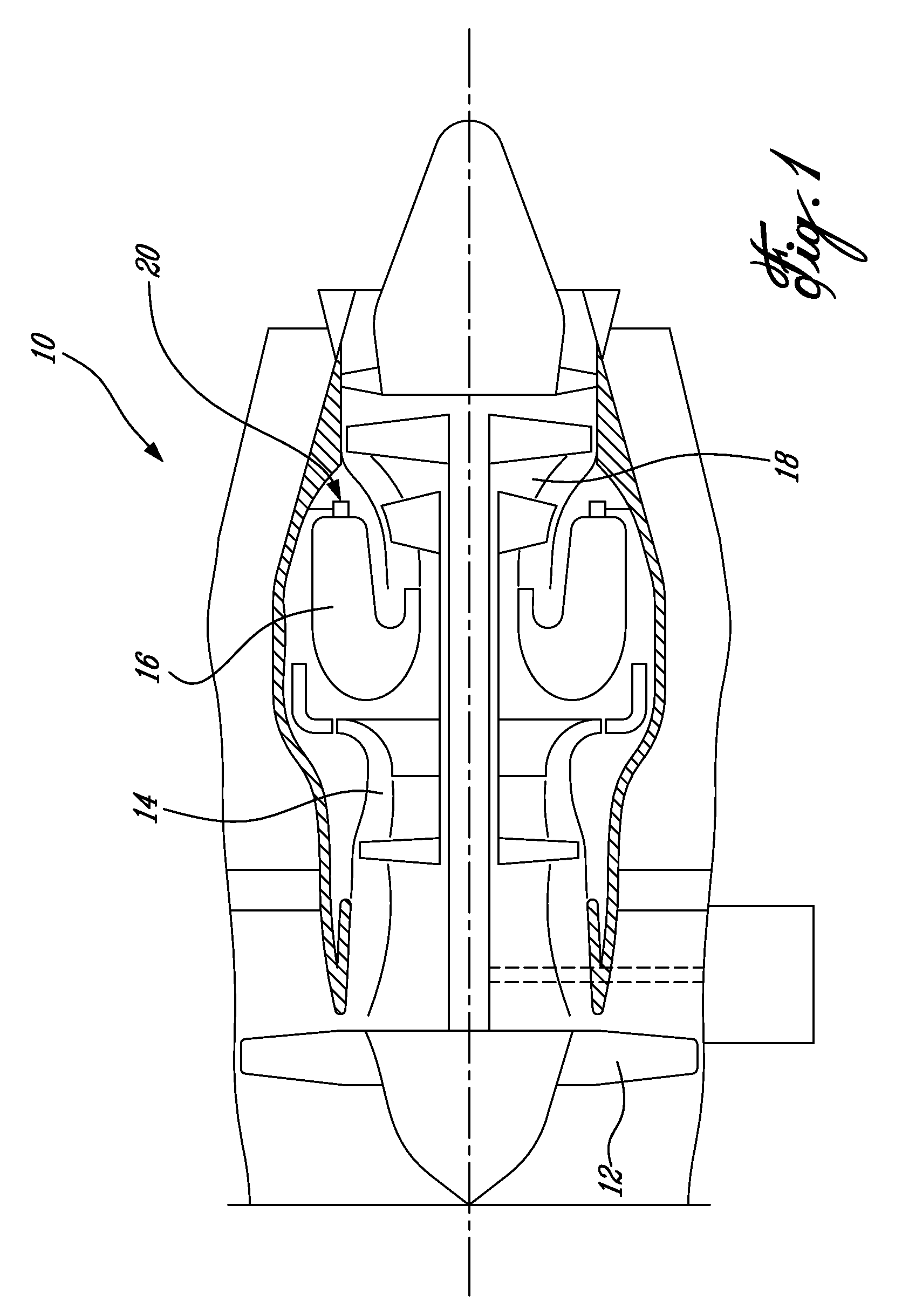
[0013]FIG. 1 illustrates a gas turbine engine 10 of a type preferably provided for use in subsonic flight, generally comprising in serial flow communication a fan 12 through which ambient air is propelled, a multistage compressor 14 for pressurizing the air, a combustor 16 in which the compressed air is mixed with fuel and ignited for generating an annular stream of hot combustion gases, and a turbine section 18 for extracting energy from the combustion gases.

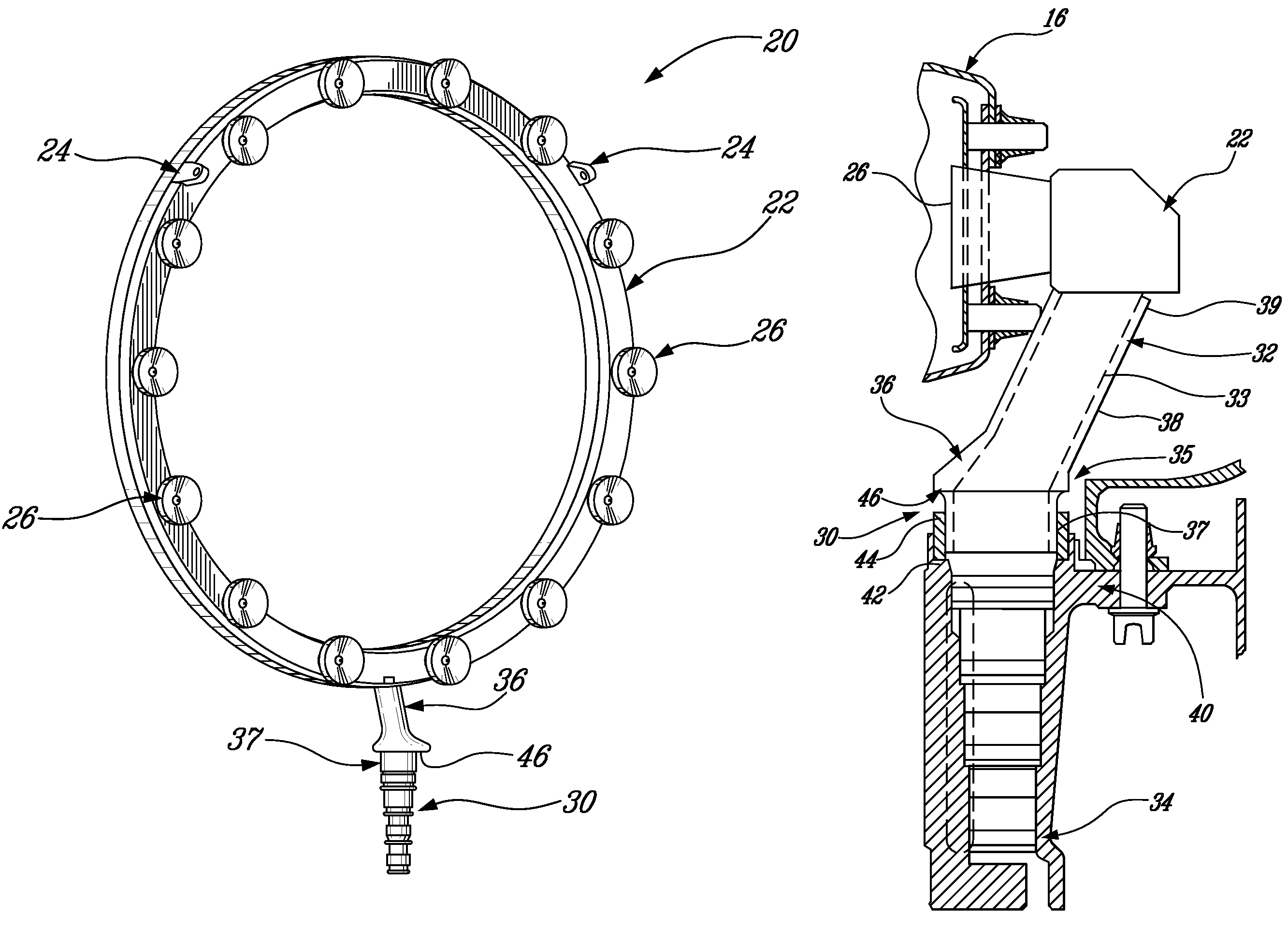
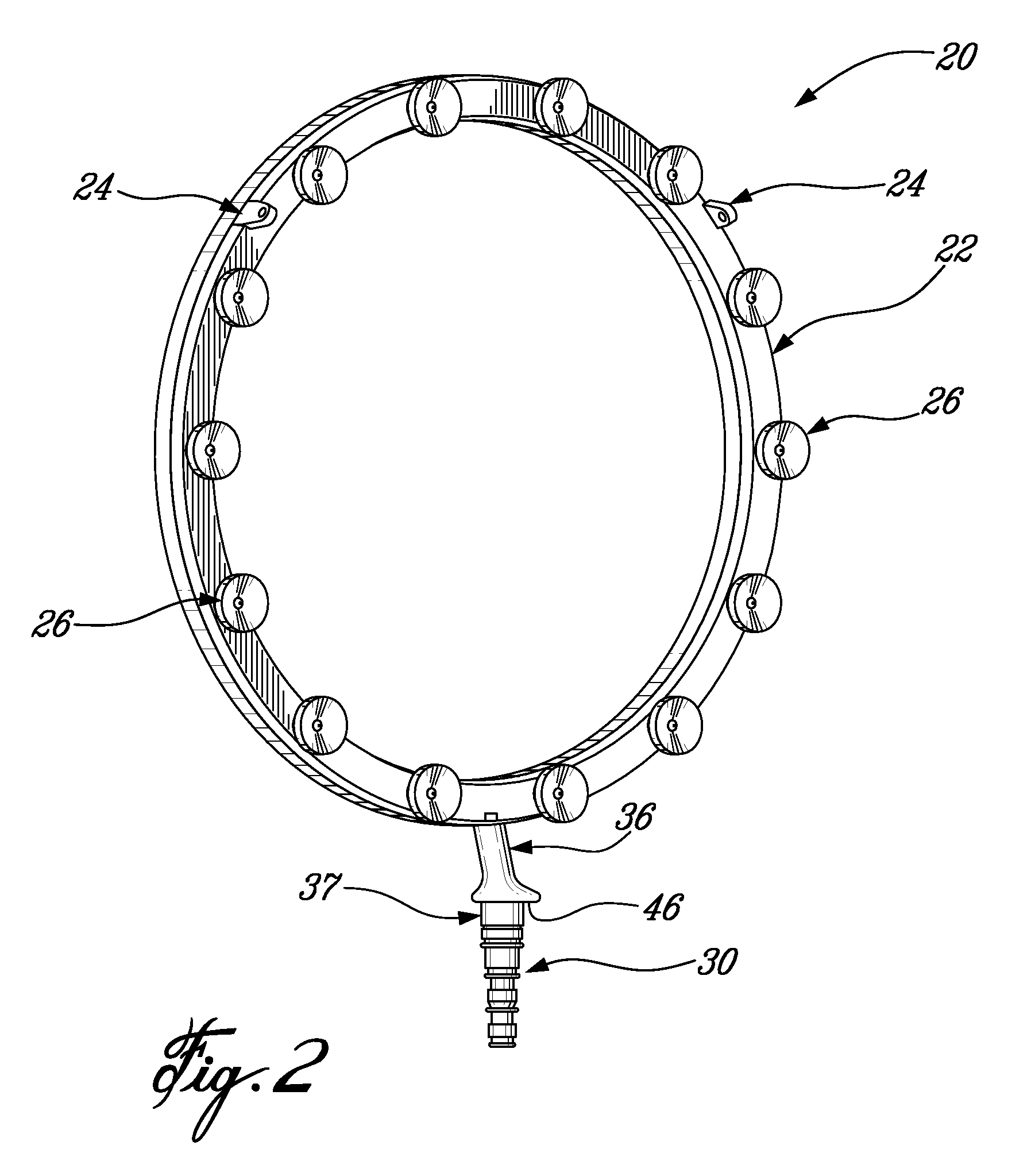
[0014]Fuel is injected into the combustor 16 of the gas turbine engine 10 by a fuel injection system 20 which is connected in fluid flow communication with a fuel source (not shown) and is operable to inject fuel into the combustor 16 for mixing with the compressed air from the compressor 14 and ignition of the resultant mixture. The fan 12, compressor 14, combustor 16, and turbine 18 are preferably all concentric about a common central longitudinal axis 11 of the gas turbine engine 10.

[0015]Referring to FIG. 2, the fuel inject...


PUM


Abstract

A mounting system for an annular internal fuel manifold disposed within a gas turbine engine includes a fuel inlet assembly having a heat shield extending about at least a portion of an inner fuel inlet tube. The heat shield has a distal end engaged with the fuel manifold and has a radially outwardly projecting shoulder proximate an opposed proximal end thereof. The proximal end of the heat shield is received within a bushing disposed within a corresponding opening of a supporting casing. The shoulder of the heat shield retains the bushing in place.

Description

TECHNICAL FIELD[0001]The technical field relates generally to internal fuel manifolds for gas turbine engines, and more specifically to a mounting configuration for an internal fuel manifold in a gas turbine engine.BACKGROUND OF THE ART[0002]Gas turbine engine internal fuel manifolds are typically located inside the engine case adjacent the engine combustor, and thus reside in an extremely hot environment. As is typical with other hardware mounted inside a gas turbine engine, complex connections are required to allow for thermal expansion and accommodate mismatches in thermal expansion which may exist between components made of different materials. Complex systems are more difficult to make and assemble, and tend to add weight and cost. Therefore, there is a continuing need to provide improvements to gas turbine internal manifold mounting systems.SUMMARY OF THE INVENTION[0003]It is an object of the present invention to provide an improved mounting configuration for an internal fuel ...

Claims


Application Information

Patent Timeline
Patent Type & Authority Patents(United States)
IPC IPC(8): F02C1/00
CPCF02C7/222F02C3/145
Inventor MORENKO, OLEGOLVER, BRYAN
Owner PRATT & WHITNEY CANADA CORP
Why Eureka
Try Eureka