Energy efficient robotic system

a robotic system and energy-efficient technology, applied in the direction of riding propulsion, machines/engines, manufacturing tools, etc., can solve the problems of reducing the energy storage capacity of most robotic systems, requiring greater energy expenditure of bipedal robots, and reducing the efficiency of controlled gaits. energy-efficient

Inactive Publication Date: 2010-04-27
TOYOTA MOTOR CO LTD
View PDF28 Cites 17 Cited by
  • Summary
  • Abstract
  • Description
  • Claims
  • Application Information

AI Technical Summary

Benefits of technology

[0008]One advantage of the present invention is that an energy-efficient bipedal robotic system is provided that relies on passive-dynamic locomotion. Another advantage of the present invention is a robotic system is provided that includes a portable, renewable energy source. Still another advantage of the present invention is that a robotic system is provided that includes a rechargeable battery that utilizes the cyclical motion of the robot during locomotion to recharge the battery. A further advantage of the present invention is that the passive-dynamic bipedal robot is energy efficient since it recaptures energy that would otherwise be lost. Still a further advantage of the present invention is that the passive-dynamic bipedal robot combines both a spring-based mechanical energy storage device with a generator-based electric energy regeneration device.

Problems solved by technology

However, this type of controlled gait is much less efficient than an actual human walking gait.
As a result, the bipedal robot requires greater energy expenditure, as compared to that of a walking comparably sized human.
However, the energy storage capability of most robotic systems remains a fundamental limitation.
Although the previously described passive-dynamic walker requires less energy than a dynamic robotic system, the passive-dynamic walker robotic system is still limited by the power requirements.

Method used


Image

  • Energy efficient robotic system
  • Energy efficient robotic system
  • Energy efficient robotic system

Examples


Embodiment Construction

)

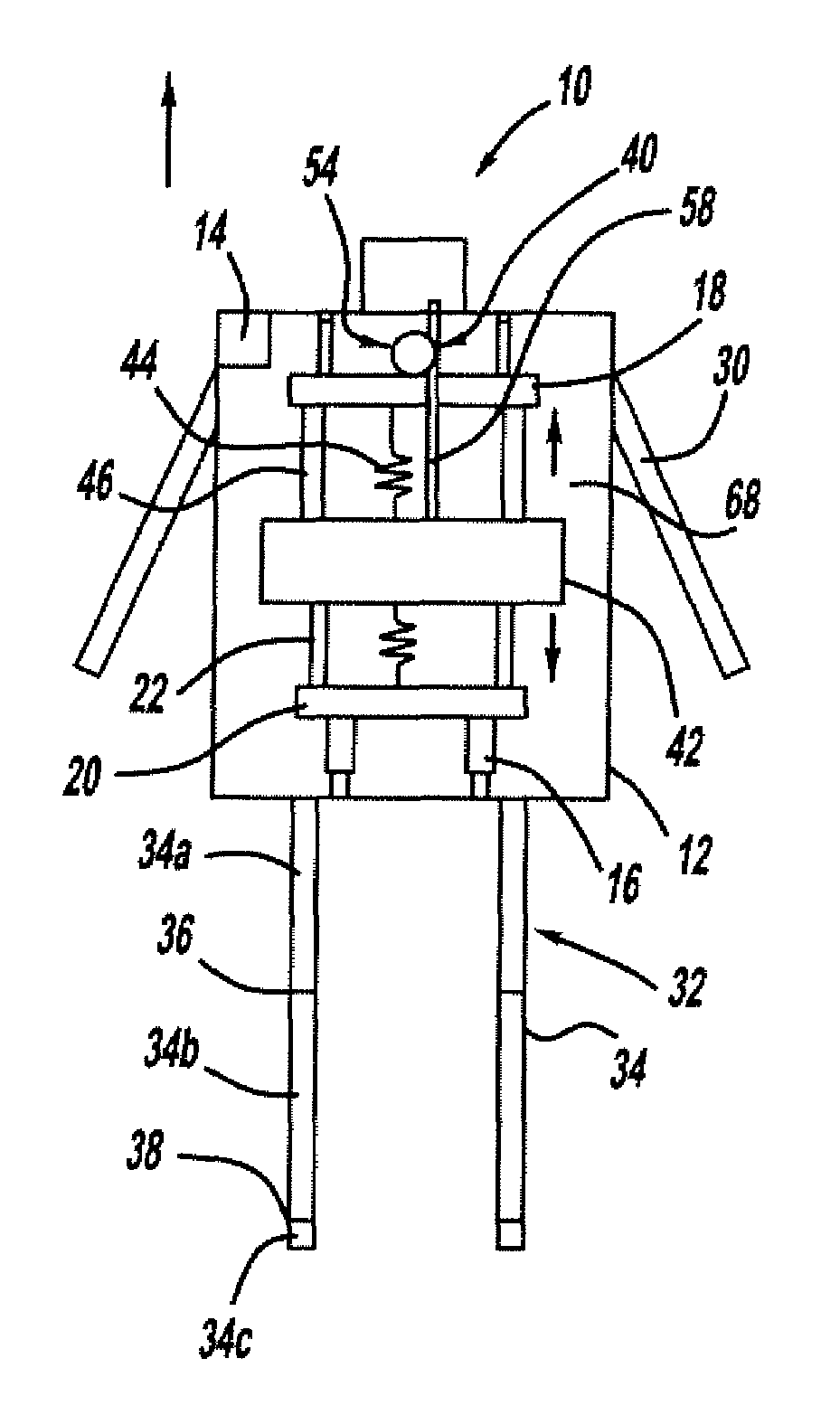
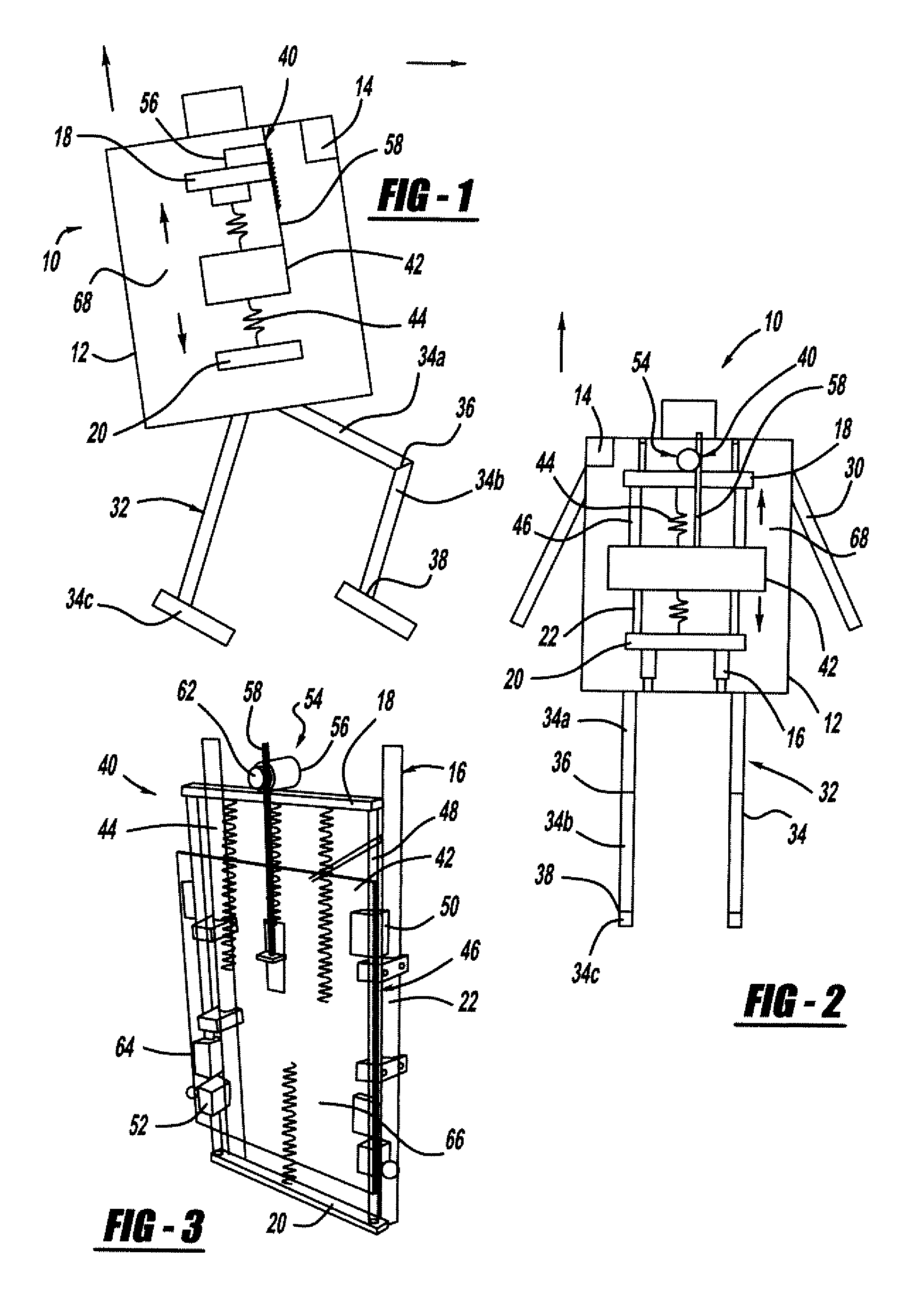
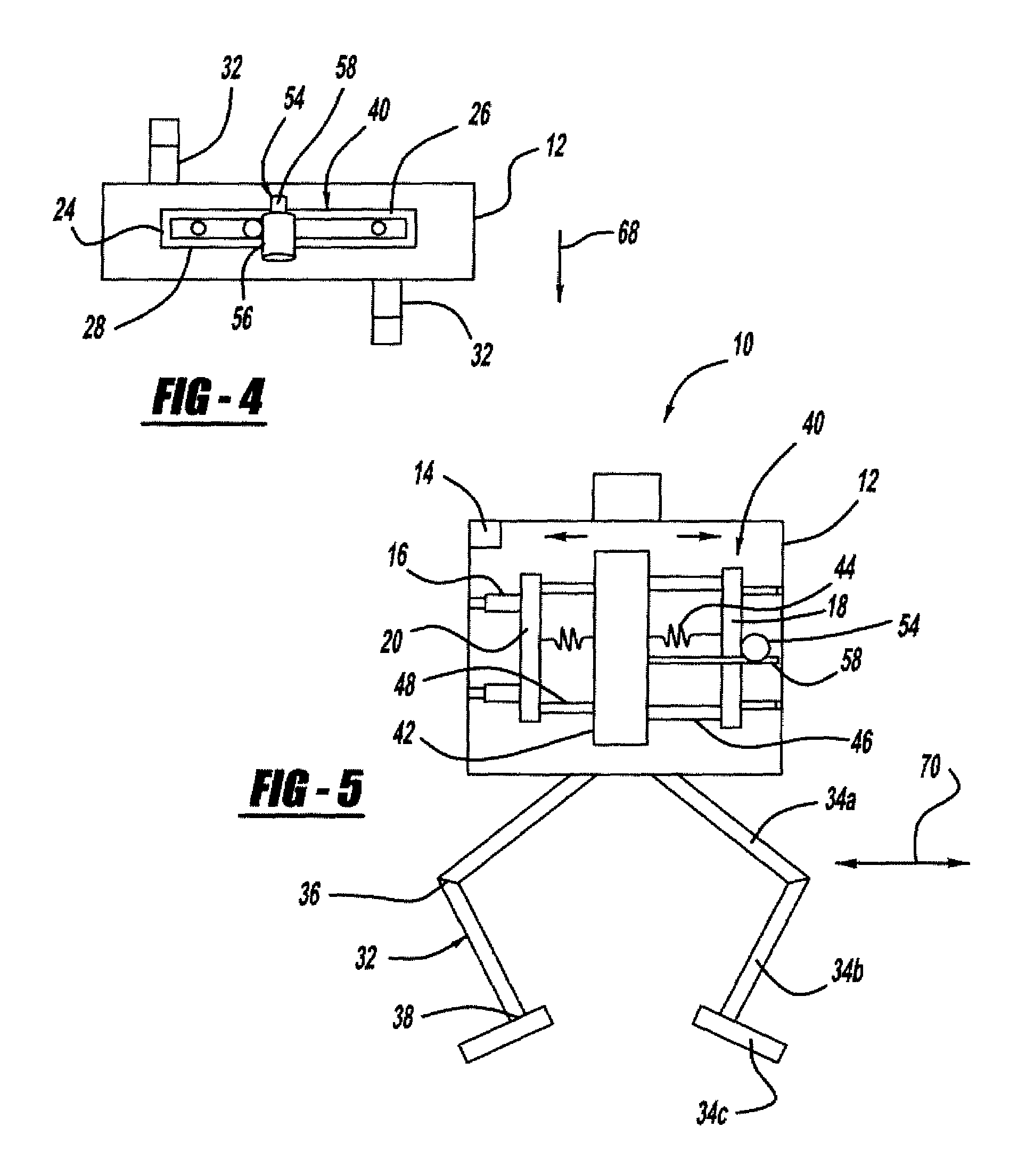
[0015]Referring to FIGS. 1-5, an energy efficient robotic system is illustrated. In this example, the robotic system is a powered, biped mobile robot 10, and in particular a passive-dynamic walking robot. The passive-dynamic walking robot 10 experiences vertically oriented cyclical or oscillatory variation during locomotion along a surface.

[0016]The robotic system 10 includes a body portion 12. The body portion 12 provides a housing. In this example, the body portion 12 has a box-like shape; however, the shape is non-limiting. The body houses a control mechanism 14 for controlling the functionality of the robot. For example, the control mechanism is a controller which includes a processor, a memory and input / output devices. The body portion 12 also houses an energy recapture mechanism, to be described, which provides a predetermined level of operational power for the robot. The body portion 12 includes a frame support structure 16. For example, the frame support structure may inclu...


PUM


Abstract

An energy efficient biped robotic system with passive-dynamic locomotion includes a body having a frame. An energy recapture mechanism is suspended within the frame. The energy recapture mechanism includes a load, a mechanical energy storage mechanism that interconnects the load and the frame, and a guide means secured to the load and the frame. A mechanical energy input mechanism interconnects the load with an electric energy generating mechanism. An output means transfers the generated electric energy to an energy storage device. The robot also includes a leg connected to the body portion. The cyclical movement of the leg during passive-dynamic locomotion is transferred to the load through the mechanical energy storage mechanism, and the resulting oscillatory movement of the load is transferred by the mechanical energy input mechanism to the electric energy generating mechanism. The generated electric energy is transferred to the energy storage device for use by the robotic system.

Description

BACKGROUND OF THE INVENTION[0001]1. Field of the Invention[0002]The present invention relates generally to an energy efficient robotic system, and more specifically, to an energy efficient robotic system with passive-dynamic locomotion.[0003]2. Description of the Related Art[0004]Various types of robotic systems are known that mimic human functions, such as locomotion, talking, manipulating an object or the like. Human walking is a complex function involving the coordinated activity of the foot, ankle, leg and hip, as well as the arms and brain. One example of a robotic system that has the ability to walk and a human-like form is a bipedal robot. The bipedal robot requires precise actuators and sophisticated control strategies, in order to mimic human walking by actively controlling every joint angle in the leg and foot, so that the center of mass of the robot remains as level as possible. However, this type of controlled gait is much less efficient than an actual human walking gait...

Claims


Application Information

Patent Timeline
Patent Type & Authority Patents(United States)
IPC IPC(8): F02B63/04
CPCH02K7/1892F03G7/08F03G5/06B62D57/032B25J5/00B25J19/00
Inventor KALIK, STEVEN F.
Owner TOYOTA MOTOR CO LTD
Why Eureka
Try Eureka