Golf swing-measuring system

a golf swing and measurement system technology, applied in the field of golf swing measurement system, can solve the problems of inability to provide the golfer with the motion of the joints and the like during the swing by simply looking at the extracted image, difficulty in finding defects in the swing form of the golfer, and points to be corrected, so as to reduce the cost of computation, reduce the erroneous recognition ratio of the attention-focused point, and achieve the effect of efficient measurement work

Inactive Publication Date: 2010-04-27
SUMITOMO RUBBER IND LTD +2
View PDF43 Cites 24 Cited by
  • Summary
  • Abstract
  • Description
  • Claims
  • Application Information

AI Technical Summary

Benefits of technology

[0012]The present invention has been made in view of the above-described problems. Therefore it is an object of the present invention to reduce a computing time period and an erroneous recognition ratio in extracting attention-focused points of a golfer's body to analyze a swing motion.

Problems solved by technology

However, these apparatuses are incapable of providing information useful for improving the golfer's swing form.
However, even though a frame corresponding to each specific motion point during the swing motion is extracted, it is impossible to provide the golfer with the motion of the joints and the like during the swing by merely looking at an extracted image.
Therefore it is difficult for the golfer to find defects in her / his swing form and points to be corrected.
Therefore the amount of computation is very large, and the coordinate of the position of each of the motion points is erroneously recognized to a high extent.
In this case, a camera is incapable of recognizing the motion points.
Consequently it is impossible to obtain the coordinate of the position of each of the motion points.
Thus there is a high probability that the swing is erroneously diagnosed.
Thus the user has a troublesome preparatory work in diagnosing her / his swing.
Therefore the amount of computation is very large, and the coordinates of the positions of the motion points are erroneously recognized to a high extent.

Method used


Image

  • Golf swing-measuring system
  • Golf swing-measuring system
  • Golf swing-measuring system

Examples


second embodiment

[0253]the present invention is described below.

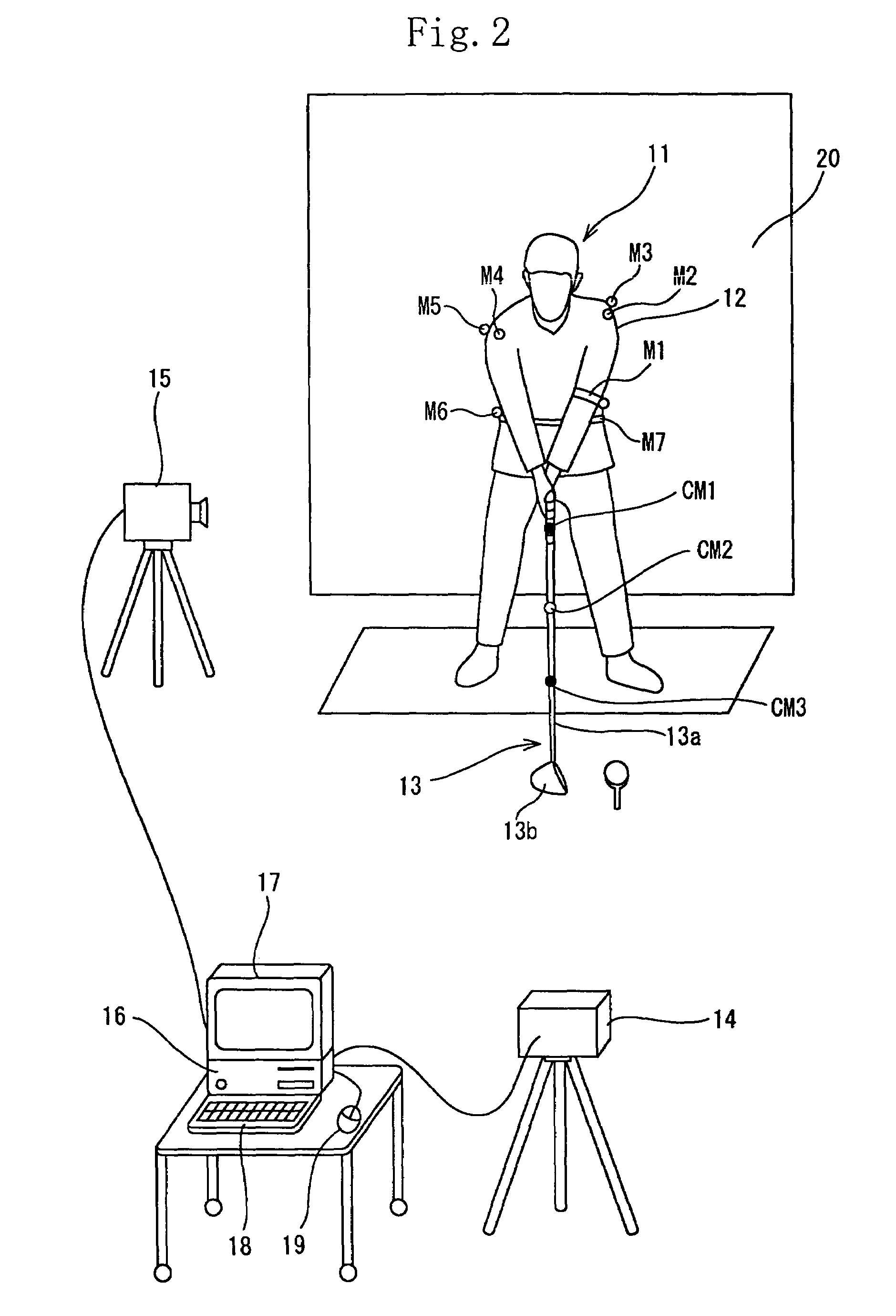
[0254]In the second embodiment, as shown in FIG. 29, a golfer 11 (right-handed) whose golf swing is to be diagnosed wears a shirt with half-length sleeve 40. No colored marks are attached to the golfer' body.

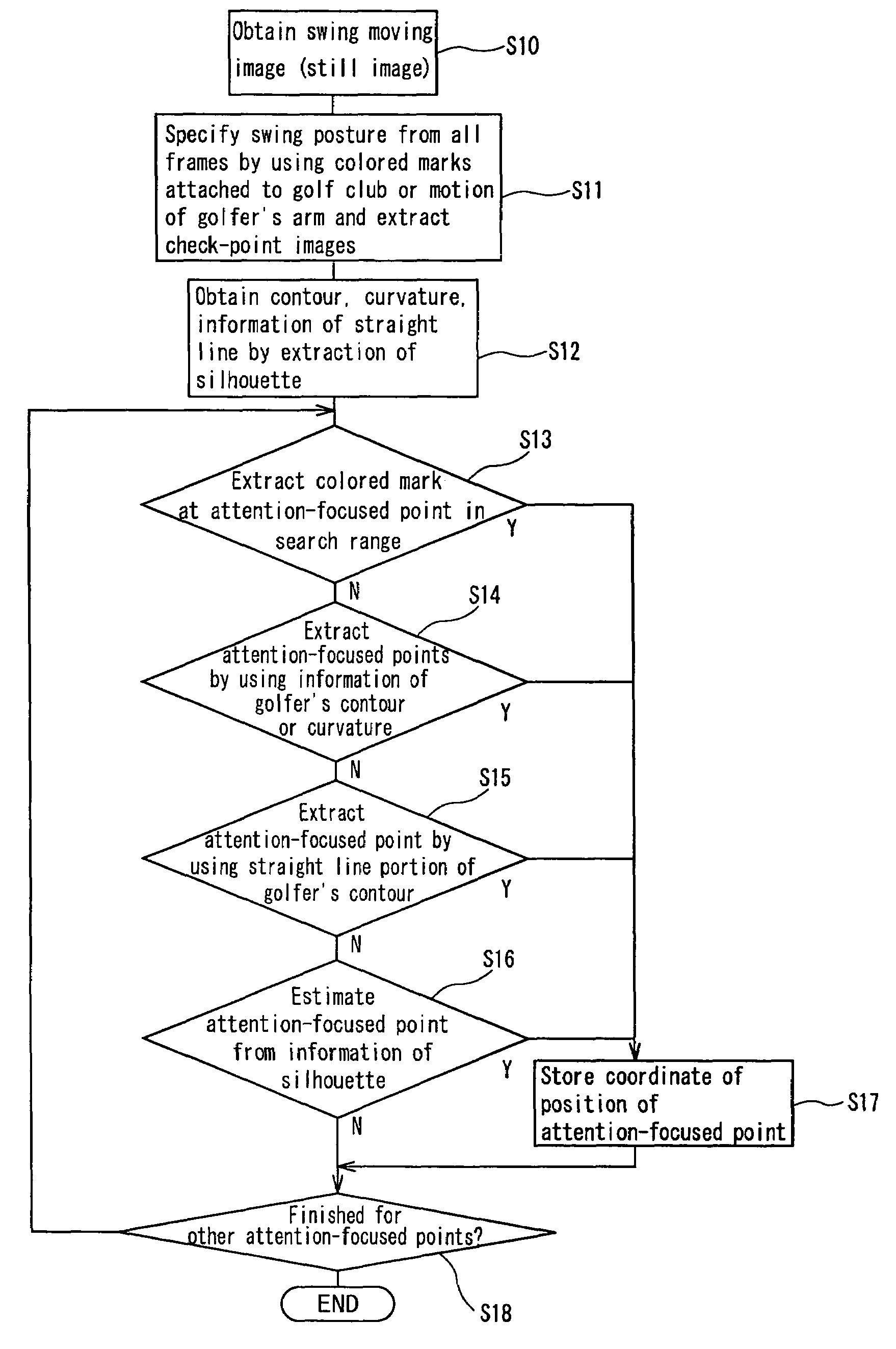
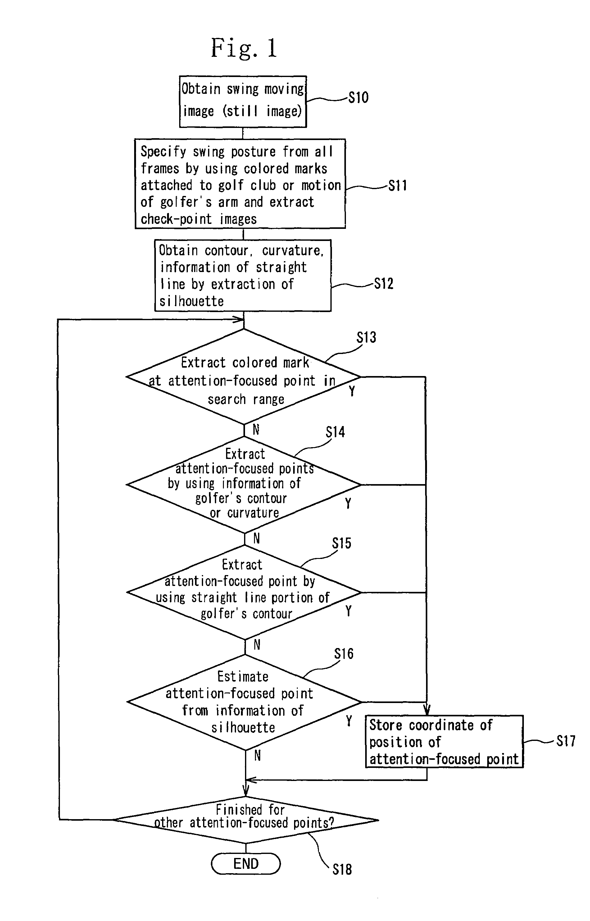
[0255]The method of obtaining coordinates of the positions of the attention-focused points present on the golfer' body 11 is described below.

[0256]Initially, a background image in which only the background 20 is photographed by the color CCD cameras 14, 15 is read. A still image for each frame of the swing image is captured into the computer 16 through the color CCD cameras 14, 15, and the data of each of obtained still images is stored in the hard disk, the memory in the computer 16 or the memory of the board.

[0257]Thereafter the following check-point images useful for diagnosing the swing are automatically extracted from a large number of still images constituting the moving image of the swing: an address image, a take-back shaft ...

first embodiment

[0259]The method of automatically extracting each check-point image is similar to that of the first embodiment and thus description thereof is omitted herein.

[0260]The coordinates of the positions of the attention-focused points necessary for diagnosing the swing of the golfer 11 are obtained for each of the check-point images.

Coordinate of Position of Right Elbow

[0261]FIG. 30 shows the method of obtaining the coordinate of the position of the right elbow which is one of the attention-focused points in the take-back left arm horizontal image (in side view).

[0262]Initially, the coordinate of the position of a grip end G is found. A vector between the colored mark CM1 nearest to the grip and the colored mark CM2 adjacent to the colored mark CM1 is found to decide the grip end. More specifically, the grip end is computed by the following equations:

Grip end=(position of colored mark CM1)−A×(vector between marks)

Center of grip={(position of colored mark CM1)+(grip end)} / 2

where A is the r...


PUM


Abstract

A golf swing-measuring system including a computer (16) for capturing a colored moving image obtained by photographing a golfer (11) who swings by gripping a golf club (13). The computer (16) selects and extracts one or more images each showing a swing posture as check-point images such as an address image, a take-back shaft 8 o'clock image, a take-back shaft 9 o'clock image, a take-back unskillful arm horizontal image, a top image, a downswing unskillful arm horizontal image, a downswing shaft 9 o'clock image, an impact image, a follow-through shaft 3 o'clock image, and a finish image and extracts from a large number of still images constituting said color moving image. Thereafter the computer (16) obtains coordinates of positions of attention-focused points that operate in said check-point images when said golfer swings.

Description

[0001]This nonprovisional application claims priority under 35 U.S.C. §119(a) on Patent Application No(s). 2004-090788 filed in Japan on Mar. 26, 2004 and 2004-091738 filed in Japan on Mar. 26, 2004, the entire contents of which are hereby incorporated by reference.BACKGROUND OF THE INVENTION[0002]1. Field of the Invention[0003]The present invention relates to a golf swing-measuring system and more particularly to a system of automatically and accurately extracting the movement of golfer's joints and the like from images in which the golfer's swing is photographed.[0004]2. Background Art[0005]There are proposed various kinds of apparatuses for photographing a golfer's swing, automatically computing information such as a flight distance, orbit, and the like of a hit golf ball by a computer, and displaying the obtained information for a golfer. These apparatuses allow the golfer to examine the flight distance, orbit, and the like of the hit ball. However, these apparatuses are incapab...

Claims


Application Information

Patent Timeline
Patent Type & Authority Patents(United States)
IPC IPC(8): A63B69/36A63B57/00A63B67/02A63B69/00G06F17/40G06T7/20
CPCA63B24/0003A63B24/0006A63B69/3608A63B69/3632A63B71/06G06T7/20A63B69/3614G06T2207/30221A63B2071/0647A63B2220/05A63B2220/807A63B2220/808A63B2220/836A63B2024/0012A63B69/36A63B69/3623
Inventor SHIRAI, YOSHIAKISHIMADA, NOBUTAKAUEDA, MASAHIKOONUKI, MASAHIDE
Owner SUMITOMO RUBBER IND LTD
Why Eureka
Try Eureka