Ring or linear cavity of all-fiber-based ultra short pulse laser system and method of operating the same

a laser system and fiber-based technology, applied in the direction of laser details, optical resonator shape and construction, excitation process/apparatus, etc., can solve the problems of high heat generation, insufficient peak power of active nanosecond fiber laser, and inability to actively modula

Inactive Publication Date: 2011-06-30
IND TECH RES INST
View PDF5 Cites 23 Cited by
  • Summary
  • Abstract
  • Description
  • Claims
  • Application Information

AI Technical Summary

Benefits of technology

[0013]The another embodiment provides a method of operating an all-fiber-based ultra short pulse laser system. The steps comprise providing an all-fiber-based ultra short pulse laser system having a pulse pump light source, a fiber saturable absorber, an assistant light source, at least a dispersion fiber, and a light coupling output; generating a broadband ASE via the pulse pump light source; making the all-fiber-based ultra short pulse laser system to achieve a passive mode locking via the fiber saturable absorber; decreasing a restoring period of the fiber saturable absorber via the assistant light source; providing dispersion compensation via the dispersion fiber to output an ultra short pulse; and partially outputting a laser passing through the all-fiber-based ultra short pulse laser system via the light coupling output.

Problems solved by technology

The peak power of the active nanosecond fiber laser is not provided efficiently enough for machining of solid and brittle material.
Furthermore, because the pulse duration is longer than a picosecond or a femtosecond of a short pulse, a great deal of heat is generated.
The passive mode locked laser is easily affected by environment, is costly and can not be actively modulated, thus, it is not available for laser machining.
If the seed power is not enough, the power of the pump light increases, and disturbs the gain fiber, a spontaneous pulse is generated in a instant short time.
However, the mode locked fiber laser 200′ must be switched to lock mode by a mechanism, and the mode locked fiber laser 200′ is sensitive to the environment, thus, the mode locked fiber laser 200′ is unstable.
This design is very complicated and needs many optical elements.

Method used


Image

  • Ring or linear cavity of all-fiber-based ultra short pulse laser system and method of operating the same
  • Ring or linear cavity of all-fiber-based ultra short pulse laser system and method of operating the same
  • Ring or linear cavity of all-fiber-based ultra short pulse laser system and method of operating the same

Examples


Embodiment Construction

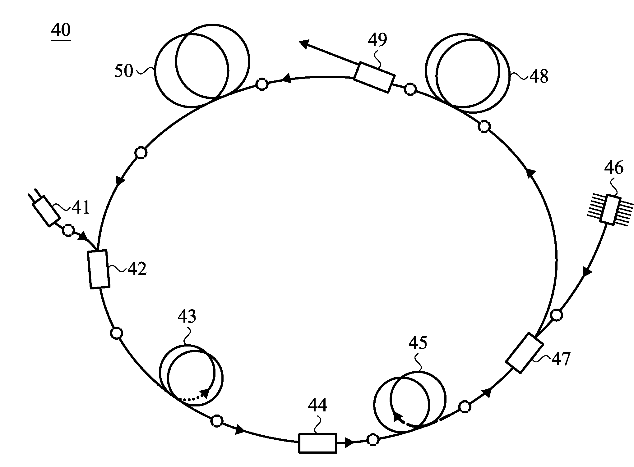
[0021]Referring to FIG. 4, a ring-cavity all-fiber-based ultra short pulse laser system 40 comprises a pulse pump light source 41, a first fiber signal pump combining unit 42, a gain fiber 43, a broadband optical isolator 44, a saturable absorber 45, an assistant light source 46, a second fiber signal pump combining unit 47, two dispersion fibers 48 and 50, and a light coupling output 49. The first fiber signal pump combining unit 42, the gain fiber 43, the broadband optical isolator 44, the saturable absorber 45, the second fiber signal pump combining unit 47, the dispersion fiber 48, the light coupling output 49 and the dispersion fiber 50 are connected in sequence to form a ring structure. The pulse pump light source 41 is connected to the first fiber signal pump combining unit 42. The assistant light source 46 is connected to the second fiber signal pump combining unit 47. In an embodiment, the first fiber signal pump combining unit 42 is a light coupler. The second fiber signal...


PUM


Abstract

A ring-cavity or linear-cavity all-fiber-based ultra short pulse laser system and method of operating the same are provided. The all-fiber-based ultra short pulse laser system includes a pulse pump light source, a gain fiber, a first fiber signal pump combining unit, a broadband optical isolator, a fiber saturable absorber, an assistant light source, a second fiber signal pump combining unit, and a light coupling output. The first fiber signal pump combining unit is respectively connected to the pulse pump light source and the gain fiber to emit broadband amplified spontaneous emission, then the broadband amplified spontaneous emission passes through the broadband optical isolator. The second fiber signal pump combining unit is respectively connected to the assistant light source and the fiber saturable absorber. An ASE signal actively provides passive mode locking of the cavity, and the light coupling output partially outputs the laser. A dispersion fiber controls the temporal width.

Description

CROSS REFERENCE TO RELATED APPLICATIONS[0001]This application claims priority of Taiwan Patent Application No. 98145761, filed on Dec. 30, 2009, the entirety of which is incorporated by reference herein.BACKGROUND OF THE INVENTION[0002]1. Field of the Invention[0003]The disclosure relates to an all-fiber-based laser system. The disclosure relates to an all-fiber-based laser system which can actively control passive mode locking.[0004]2. Description of the Related Art[0005]A pulse fiber laser has potential to be used in applications such as; machining of solid and brittle material, in medical examinations and in wavelength transformation. Maximum peak power output is mainly provided by an active nanosecond fiber laser and a passive mode locked laser. However, the above two lasers have the following disadvantages. The peak power of the active nanosecond fiber laser is not provided efficiently enough for machining of solid and brittle material. Furthermore, because the pulse duration i...

Claims


Application Information

Patent Timeline
Patent Type & Authority Applications(United States)
IPC IPC(8): H01S3/083H01S3/30
CPCH01S3/06725H01S3/06791H01S3/1618H01S3/1061H01S3/1118H01S3/094076
Inventor CHANG, YAO-WENHUANG, CHIEN-MING
Owner IND TECH RES INST
Why Eureka
Try Eureka