Solid state imaging apparatus and method of driving the same

a technology of solid-state imaging and imaging apparatus, which is applied in the direction of instruments, television systems, and scanning details of television systems, can solve the problems of increasing noise and more serious problems of the influence of the holding capacitor, and achieve the effect of suppressing the noise generated and not increasing the blanking period

Inactive Publication Date: 2012-04-10
CANON KK
View PDF16 Cites 29 Cited by
  • Summary
  • Abstract
  • Description
  • Claims
  • Application Information

AI Technical Summary

Benefits of technology

[0010]The present invention has been made in view of the above described problems. An object of the present invention is to provide a solid-state imaging apparatus and a method of driving the solid-state imaging apparatus, which are capable of suppressing a noise generated in synchronization with a sampling pulse during a vertical transfer period without increasing a blanking period.

Problems solved by technology

However, the solid-state imaging apparatus, to which the above described reading method is applied, has the following problems.
Therefore, the noise tends to be increased, as the holding capacitor to be simultaneously driven is increased so as to thereby increase the magnitude of transient change caused in the charge and discharge current of the holding capacitor during the sampling operation.
As the number of pixels is increased to thereby increase the holding capacitor, the influence of the holding capacitor appears as a more serious problem.

Method used


Image

  • Solid state imaging apparatus and method of driving the same
  • Solid state imaging apparatus and method of driving the same
  • Solid state imaging apparatus and method of driving the same

Examples


first embodiment

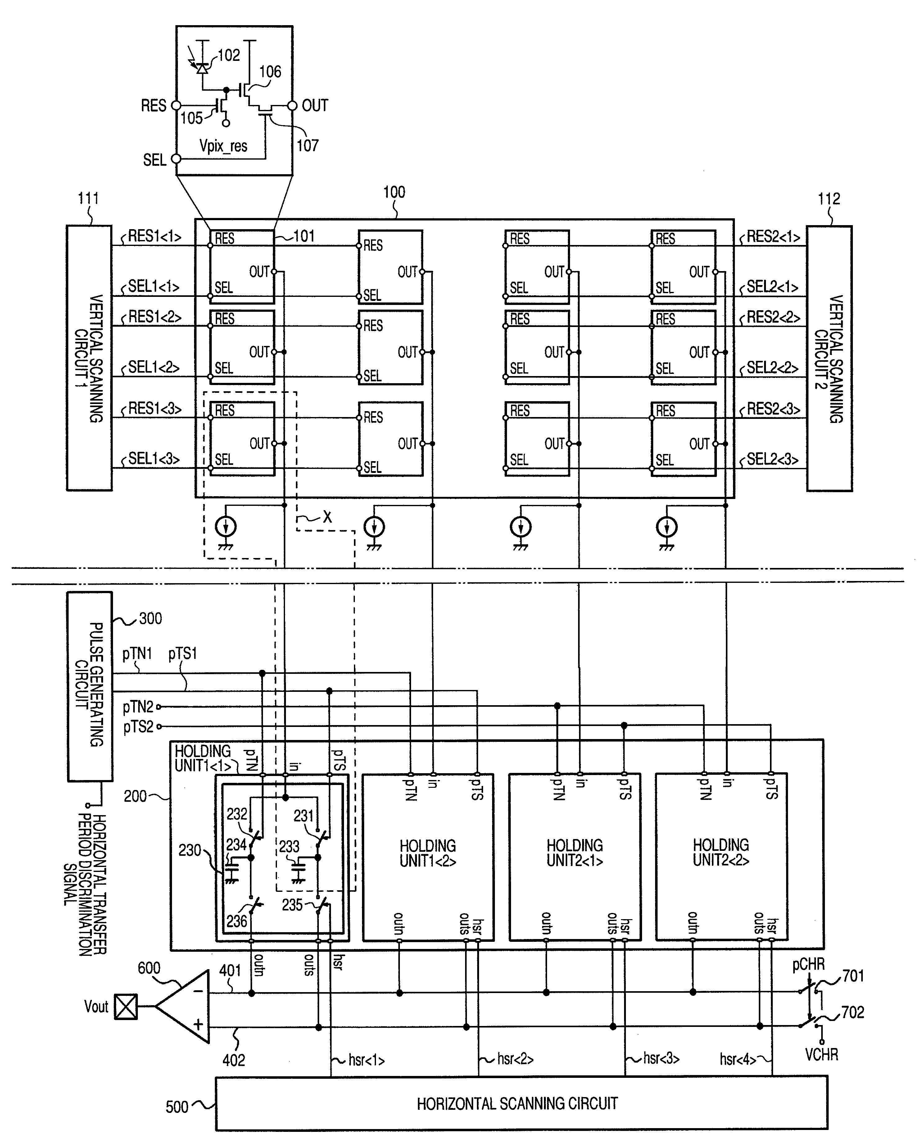
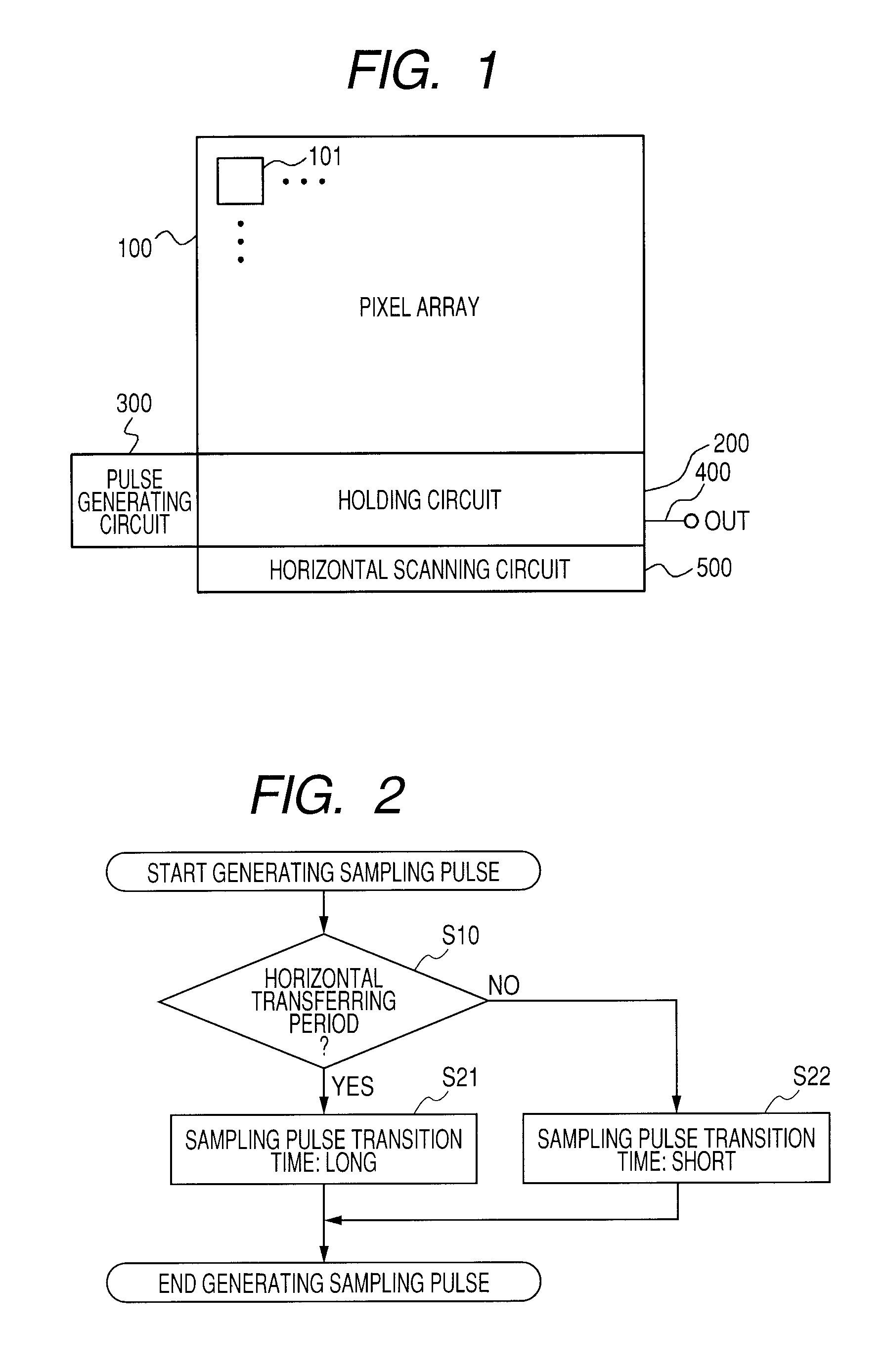
[0031]FIG. 1 is a block diagram of a solid-state imaging apparatus according to a first embodiment of the present invention. A pixel array 100 is configured by a plurality of pixels 101. A holding circuit 200 is configured by first and second holding units for holding pixel signals input from the pixel array 100. A pulse generator circuit 300 generates a sampling pulse used in the holding circuit 200. A horizontal common output line 400 outputs the pixel signals held in the holding circuit 200 to the outside. A horizontal scanning circuit 500 transfers the pixel signals from the holding circuit 200 to the horizontal common output line 400.

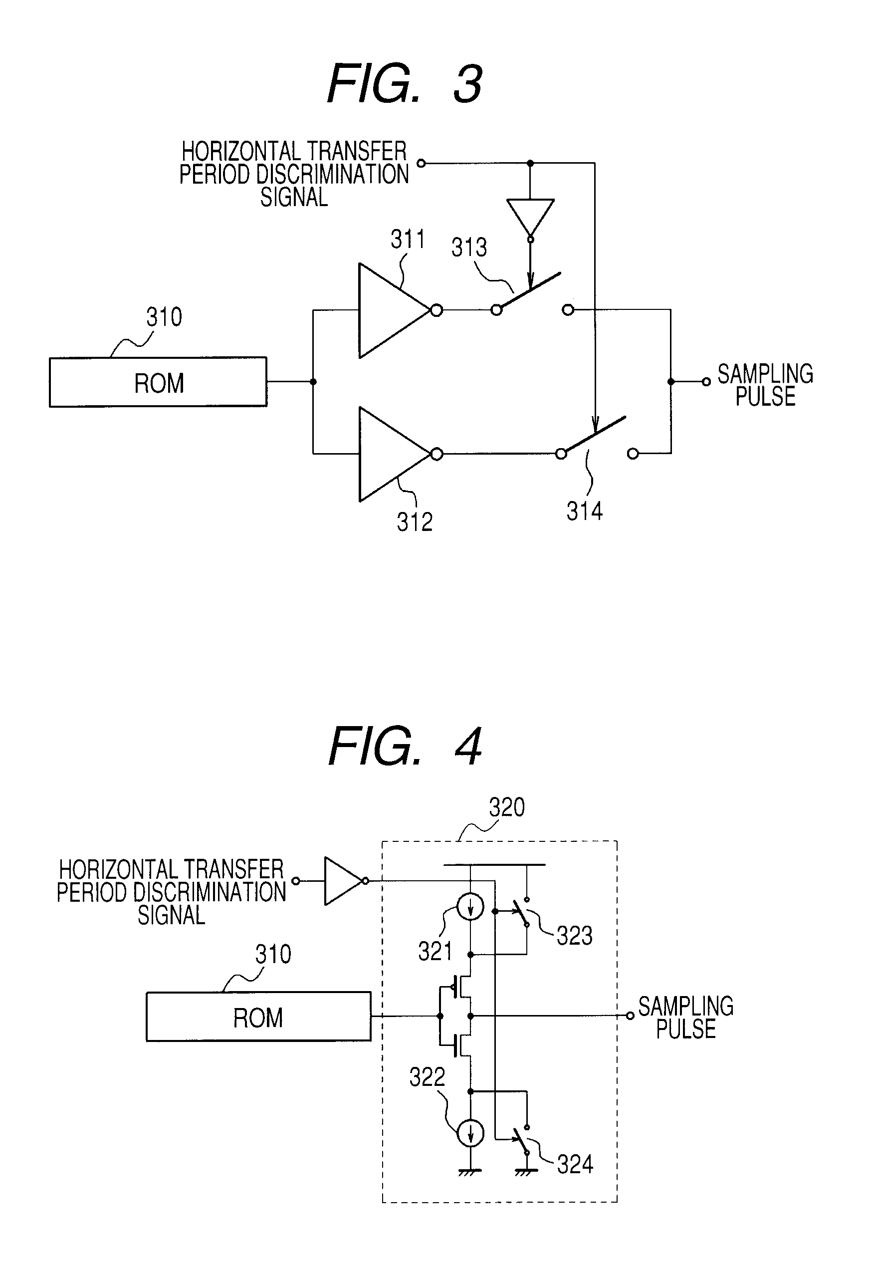
[0032]FIG. 2 is a flow chart describing an operation of the pulse generator circuit 300 of FIG. 1. In FIG. 2, when the generation of the sampling pulse is started, the pulse generator circuit 300 first discriminates whether or not the present time is in a horizontal transfer period (step S10). Note that the “horizontal transfer period” in the prese...

second embodiment

[0060]FIG. 10 shows a solid-state imaging apparatus according to a second embodiment of the present invention. In FIG. 10, the pixel array 100 is configured by pixels 101 arranged in M rows and N columns (where M and N are integers). Note here that the configuration of the pixel 101 is different from the configuration according to the first embodiment, and is configured as a four Tr type pixel including a transfer Tr 103 and a FD (floating diffusion) 104.

[0061]The outputs of the pixels 101 are output by vertical output lines 108 and 109 provided for each column, in such a manner that the output of the pixel 101 of an odd-numbered row and the output of the pixel 101 of an even-numbered row are respectively output by the separate signal lines. The holding circuit 200 is configured by (N / 2) holding units 1 which are respectively provided for each column from the first column to the (N / 2)th column, and (N / 2) holding units 2 which are respectively provided for each column from the (1+N / 2...

third embodiment

[0075]FIG. 13 shows a solid-state imaging apparatus according to a third embodiment of the present invention. However, only the difference from the first and second embodiments will be described here. In FIG. 13, the holding circuit 200 is configured by N holding units 1 each of which is provided for each column and each of which is configured by the amplifier circuit 220 and a first line memory 250, and N holding units 2 each of which is similarly provided for each column and each of which is configured by a second line memory 260.

[0076]FIG. 14 is an operation timing chart showing a driving method of the solid-state imaging apparatus of FIG. 13. In FIG. 14, during the period of t1, the first line memory 250 is reset, and the reset level of the pixel of the first row is clamped in a clamp capacitor 229.

[0077]In the period of t2, the noise level of the amplifier circuit 220 is sampled and held in a first noise signal holding capacitor 254 (Ctn1) in the first line memory 250 by a samp...


PUM


Abstract

In a solid-state imaging apparatus, during a horizontal scanning period, a pixel signal is written in a first holding unit, while a horizontal scanning circuit outputs, to the horizontal common output line, the other pixel signal held by a second holding unit. And, a transition time of an edge of a sampling pulse during the horizontal scanning period is set longer than a transition time of an edge of the sampling pulse during a time period other than the horizontal scanning period.

Description

BACKGROUND OF THE INVENTION[0001]1. Field of the Invention[0002]The present invention relates to a solid-state imaging apparatus used for a scanner, a video camera, a digital still camera, and the like, and to a method of driving the solid-state imaging apparatus.[0003]2. Description of the Related Art[0004]In recent years, there has been a request for increasing the number of pixels in a CMOS solid-state imaging apparatus. When the number of pixels is increased, the number of pixels to be read during one horizontal scanning period is increased, so that the reading speed of pixel signals needs to be increased. The techniques to cope with the increase in the reading speed include a method disclosed in Japanese Patent Application Laid-Open No. 2007-194720 (hereinafter referred to as Patent Document 1).[0005]In Patent Document 1, it is described that the image reading speed can be increased by reducing the vertical transfer wait period in such a manner that pixels of a solid-state imag...

Claims


Application Information

Patent Timeline
Patent Type & Authority Patents(United States)
IPC IPC(8): H04N3/14H04N5/335H01L27/00H04N5/357H04N5/369H04N5/374H04N5/378
CPCH04N25/617H04N25/616H04N25/767H04N25/745
Inventor KATO, SATOSHITOTSUKA, HIROFUMI
Owner CANON KK
Why Eureka
Try Eureka