Brushless motor

a brushless motor and motor body technology, applied in the direction of dynamo-electric machines, electrical equipment, supports/enclosements/casings, etc., can solve the problems of increasing the height dimension of the coupler, affecting the operation of the motor, so as to reduce the vertical dimension

Inactive Publication Date: 2010-05-04
HITACHI ASTEMO LTD
View PDF10 Cites 25 Cited by
  • Summary
  • Abstract
  • Description
  • Claims
  • Application Information

AI Technical Summary

Benefits of technology

[0008]It is a general object of the present invention to provide a brushless motor with a coupler that has a reduced vertical dimension.
[0010]Another object of the present invention is to provide a brushless motor, which has a low power requirement and a high response speed.
[0011]Still another object of the present invention is to provide a brushless motor, which can be used stably over a long period of time.
[0013]The brushless motor includes connectors that project radially inwardly of the coupler, in contrast to connectors that project radially outwardly from the coupler. The connectors and the terminal rods, and hence the annular member and the plug, can be of the same height. The height dimension of the coupler can therefore be reduced, and the brushless motor can be reduced in size.
[0014]Preferably, the bridges are provided as pairs of adjacent bridges, wherein the adjacent bridges in each of the pairs extend parallel to each other. With this structure, the number of times that the leads have their angle changed is reduced when the connectors and the leads are joined to each other, with the result that the tact time required to produce the brushless motor can be shortened.

Problems solved by technology

If the connectors and the terminal rods are of the same height, then the connectors interfere with the terminal rods.
One problem that occurs when the terminal rods and the connectors have different heights is that the coupler has an increased height dimension.
Accordingly, it has been difficult to reduce the size of conventional brushless motors.

Method used


Image

  • Brushless motor
  • Brushless motor
  • Brushless motor

Examples


Embodiment Construction

[0028]A brushless motor according to a preferred embodiment of the present invention, for use on an internal combustion engine in an automobile, will be described below with reference to the accompanying drawings.

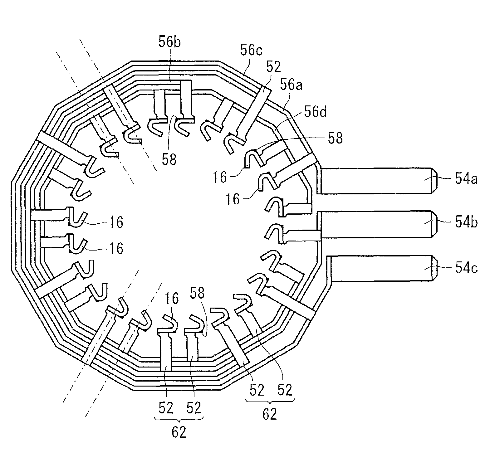
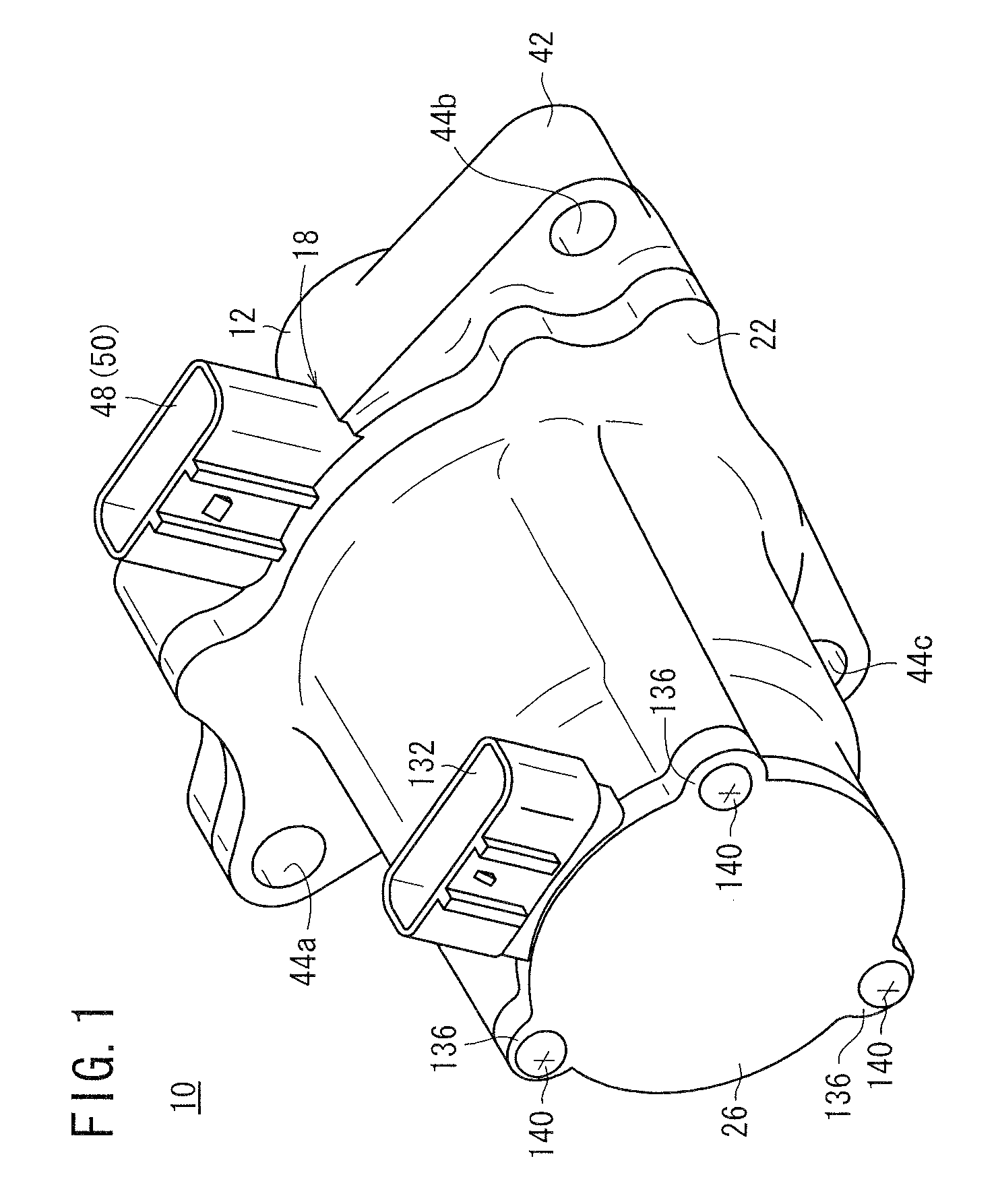
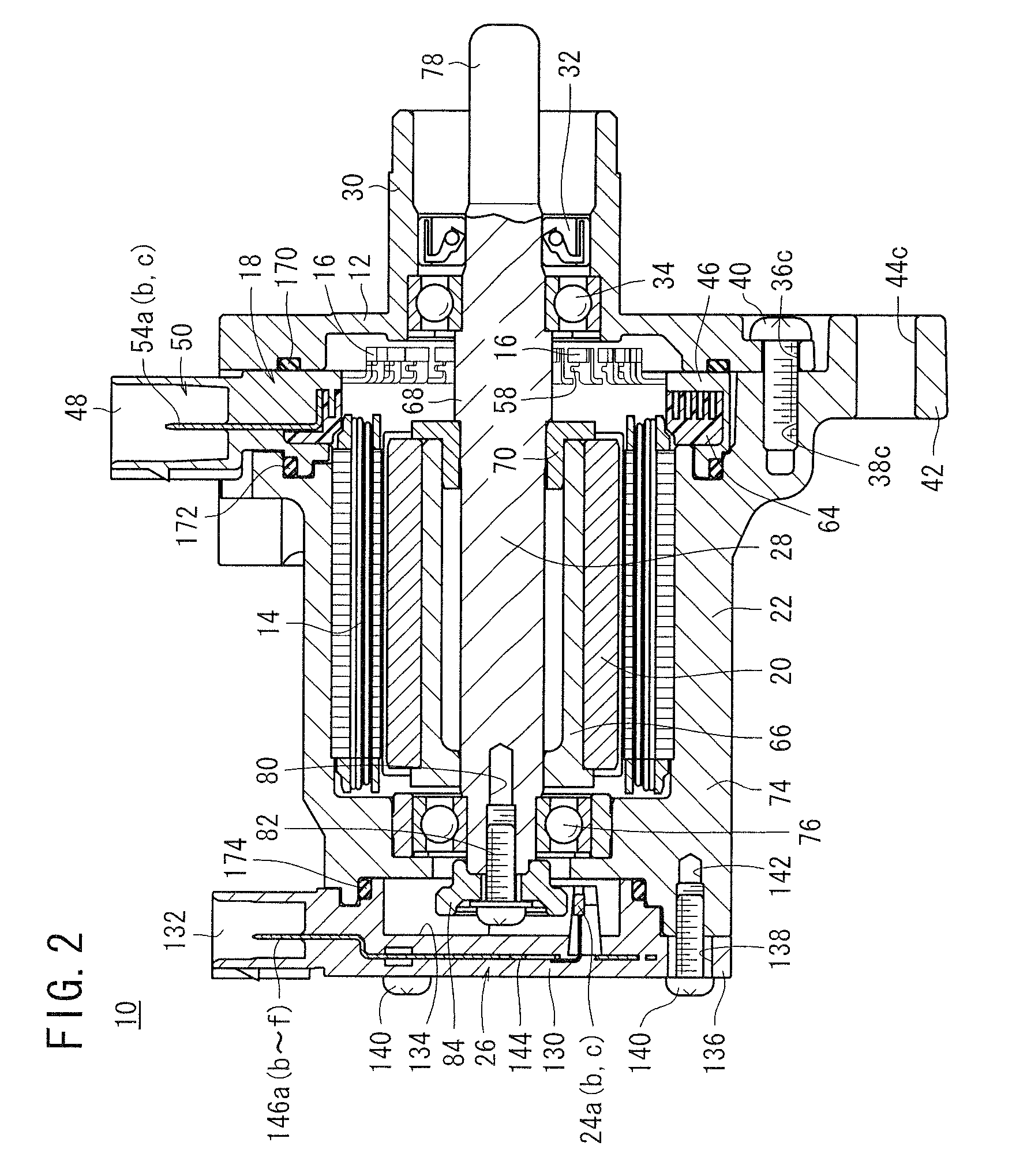
[0029]FIGS. 1 through 3 are perspective, vertical sectional side elevational, and rear elevational views, respectively, of the brushless motor, generally denoted by 10, according to the preferred embodiment of the present invention. The brushless motor 10 comprises a holder base 12 that is coupled to the cylinder head of an internal combustion engine, a first coupler 18 having connectors 16 electrically connected to an electromagnetic coil 14 (see FIG. 2), a casing 22 housing the electromagnetic coil 14 and a main magnet 20 therein, and a second coupler 26 closing an open end of the casing 22 and accommodating three Hall ICs 24a through 24c (pole position detecting elements), which are securely positioned in the second coupler 26. A shaft 28 is centrally inserted axially in...


PUM


Abstract

A brushless motor has a first coupler that includes a molded body with an annular member and a plug integrally combined with a peripheral side wall of the annular member. The plug houses terminal rods therein. Bridges project radially inward from an inner peripheral wall surface of the annular member. Connectors joined to respective leads that extend from an electromagnetic coil are mounted on radial inner ends of the bridges. The bridges axe provided in pairs of adjacent bridges. In each of such pairs, the bridges project in parallel with each other from an inner peripheral wall surface of the annular member.

Description

BACKGROUND OF THE INVENTION[0001]1. Field of the Invention[0002]The present invention relates to a brushless motor having magnets that rotate in an electromagnetic coil to generate power.[0003]2. Description of the Related Art[0004]In recent years, brushless motors have increasingly been combined with automotive internal combustion engines. One known type of brushless motor, which has been applied and used in this manner, includes a cylindrical electromagnetic coil securely positioned inside a casing together with magnets, which are rotatably disposed in the cylindrical electromagnetic coil.[0005]Leads extend from the electromagnetic coil and are connected to respective connectors projecting from a coupler. The connectors are electrically connected to three terminals whose inside and outside diameters are different from each other. Terminal rods, which extend from the terminals, provide respective contacts in three phases, i.e., U, V, and W phases. The connectors thus serve as elect...

Claims


Application Information

Patent Timeline
Patent Type & Authority Patents(United States)
IPC IPC(8): H02K7/00
CPCH02K5/08H02K29/08H02K5/225
Inventor OHUCHI, TAKUYAOMORI, SHIGEOOYAMA, HIROSHIUCHIMURA, KATSUHIRO
Owner HITACHI ASTEMO LTD
Why Eureka
Try Eureka