
Thermally assisted magnetic head

a magnetic head and thermal assisted technology, applied in special recording techniques, instruments, record information storage, etc., can solve the problem of difficult to intensely heat a desired point, and achieve the effect of high-density recording

Active Publication Date: 2010-05-04
TDK CORPARATION
View PDF9 Cites 12 Cited by
  • Summary
  • Abstract
  • Description
  • Claims
  • Application Information

AI Technical Summary

Benefits of technology

The present invention relates to a thermally assisted magnetic head for hard disk drives. The invention aims to suppress the emission of near-field light from the part other than the cusp portion of the near-field light generator plate, which can make it difficult to intensively heat a desired point only. The invention proposes a near-field light generator plate with a thermally assisted magnetic head that can suppress the generation of near-field light from the other end of the near-field light generator plate, which is opposite to the cusp portion. This allows for selective heating of a desired portion of the medium and high-density recording. The invention also includes a head gimbal assembly and a hard disk drive with the thermally assisted magnetic head.

Problems solved by technology

In the case of the magnetic heads in the above-cited Documents, however, the near-field light was generated from the part other than the cusp portion, particularly, from the other end opposite to the cusp portion and it was sometimes difficult to intensively heat a desired point only.

Method used


Image

  • Thermally assisted magnetic head
  • Thermally assisted magnetic head
  • Thermally assisted magnetic head

Examples


Embodiment Construction

[0034]Embodiments for carrying out the present invention will be described below in detail with reference to the accompanying drawings. In each of the drawings, the same elements will be denoted by the same reference numerals. It is also noted that the dimensional ratios in and between the constituent elements in the drawings are arbitrary, for easier understanding of the drawings.

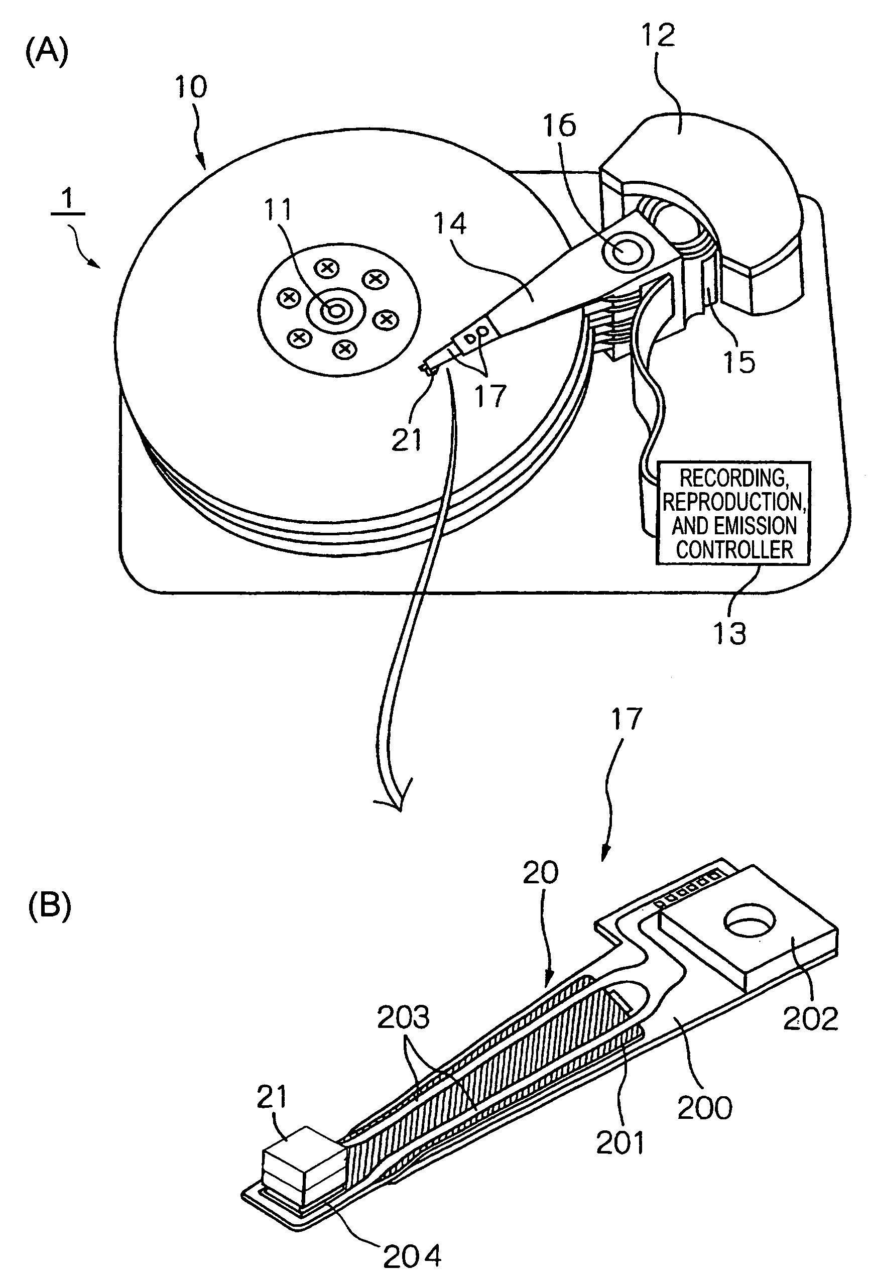
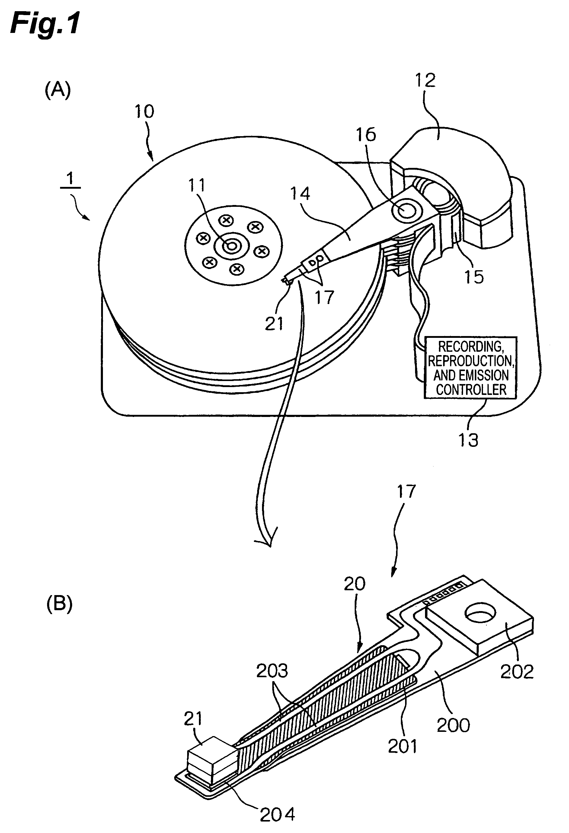
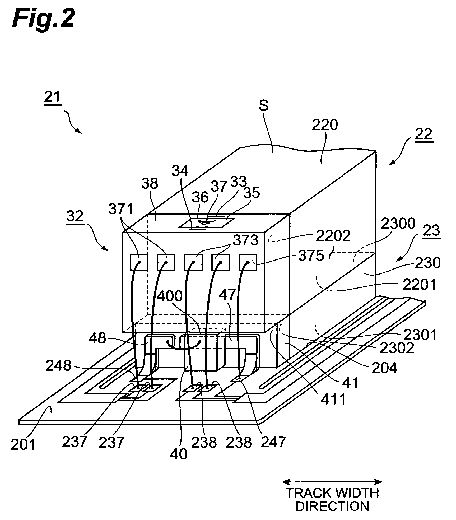
[0035]FIG. 1 is a perspective view schematically showing a configuration of a major part in an embodiment of the hard disk drive and HGA (head gimbal assembly) according to the present invention. FIG. 2 is an enlarged perspective view of a part near a thermally assisted magnetic head 21 in FIG. 1. In the perspective view of the HGA, the side of the HGA facing a surface of a magnetic disk is illustrated up.

[0036](Hard Disk Drive)

[0037]In (A) of FIG. 1, the hard disk drive 1 has magnetic disks (recording medium) 10 consisting of a plurality of magnetic recording media to rotate around a rotation shaft of spi...


PUM

PropertyMeasurementUnit
thicknessaaaaaaaaaa
thicknessaaaaaaaaaa
thickaaaaaaaaaa

Abstract

A thermally assisted magnetic head has a medium-facing surface facing a medium, and comprises: a waveguide an end face of which is exposed in the medium-facing surface; an electroconductive near-field light generator plate disposed on a medium-facing surface of the waveguide so that a principal face thereof faces the medium; and an electroconductive near-field light scatter plate disposed on the medium-facing surface of the thermally assisted magnetic head so that a principal face thereof faces the medium; when viewed from a direction perpendicular to the medium-facing surface, the near-field light generator plate has a cusp portion at an end; when viewed from the direction perpendicular to the medium-facing surface, the near-field light scatter plate is arranged along the other end opposite to the cusp portion of the near-field light generator plate; when viewed from the direction perpendicular to the medium-facing surface, a width of the near-field light scatter plate in a first direction perpendicular to a direction connecting the cusp portion and the other end of the near-field light generator plate is larger than a width in the first direction of the near-field light generator plate.

Description

BACKGROUND OF THE INVENTION[0001]1. Field of the Invention[0002]The present invention relates to a thermally assisted magnetic head for writing of signals by thermally assisted magnetic recording, and to a head gimbal assembly (HGA) with this thermally assisted magnetic head, and a hard disk drive with this HGA.[0003]2. Related Background Art[0004]As the recording density of the hard disk drive increases, further improvement is demanded in the performance of the thin film magnetic head. In order to increase the recording density, a recording medium is made of a magnetic material with large Ku and the so-called thermally assisted magnetic recording is proposed as a method of applying heat to the recording medium right before application of a writing magnetic field to lower the coercivity of the magnetic material, and then performing writing.[0005]As examples of such thermally-assisted magnetic head recording apparatus, Japanese Patent Application Laid-Open No. 2001-255254, Japanese P...

Claims


Application Information

Patent Timeline
Patent Type & Authority Patents(United States)
IPC IPC(8): G11B5/02
CPCG11B5/02G11B5/314G11B2005/0021G11B2005/0002
Inventor TANAKA, KOSUKESHIMAZAWA, KOJI
Owner TDK CORPARATION
Learn More