High conductivity ground planes for integrated lead suspensions

a ground plane structure and lead suspension technology, applied in the direction of integrated arm assemblies, instruments, record information storage, etc., can solve the problems of reducing the signal performance characteristics of traces, and achieve the effect of high conductivity and high conductivity material

Active Publication Date: 2010-05-04
HUTCHINSON TECH
View PDF31 Cites 35 Cited by
  • Summary
  • Abstract
  • Description
  • Claims
  • Application Information

AI Technical Summary

Benefits of technology

[0005]The present invention is an integrated lead flexure or suspension including an insulating layer, a plurality of traces on the insulating layer and a stainless steel base layer on the side of the insulating layer opposite the traces. The traces are free of a conductive shi

Problems solved by technology

These electrical characteristics can reduce the signal performance c

Method used


Image

  • High conductivity ground planes for integrated lead suspensions
  • High conductivity ground planes for integrated lead suspensions

Examples


Embodiment Construction

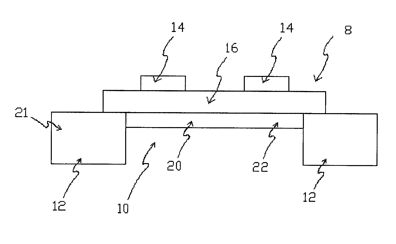
[0008]FIG. 1 is a cross sectional view of a portion of an integrated lead flexure 8 having a high conductivity ground plane structure 10 in accordance with one embodiment of the invention. As shown, flexure 8 includes a stainless steel base layer 12, a plurality of leads or traces 14 (two are shown for purposes of example only) and a dielectric or insulating layer 16 separating the traces from the base layer. With the exception of the ground plane structure 10 and its methods of manufacture described below, flexure 8 can be of any conventional or otherwise known structure and manufactured using any conventional or otherwise known additive, subtractive or other processes. Although the flexure 8 can have additional structures and layers (not shown) such as an insulating cover layer over the traces 14, flexure 8 is free from a conductive shield layer or other structure that is electrically insulated from and over the traces (i.e., over the side of the traces 14 opposite the insulating ...


PUM


Abstract

An integrated lead flexure or suspension including an insulating layer, a plurality of traces on the insulating layer and a stainless steel base layer on the side of the insulating layer opposite the traces. The traces are free of a conductive shield layer on the side opposite the insulating layer. One or more voids extend through the stainless steel layer below the traces. The voids are filled with a high conductivity metal layer.

Description

FIELD OF THE INVENTION[0001]The invention relates generally to integrated lead suspensions used in disk drives. In particular, the invention is a high conductivity ground plane structure for an integrated lead suspension.BACKGROUND OF THE INVENTION[0002]Integrated lead or wireless suspensions used to support the sliders and read / write heads in magnetic disk drives are well known and disclosed, for example, in the Akin, Jr. et al. U.S. Pat. No. 5,796,552 and the Shiraishi et al. U.S. Pat. No. 6,891,700. These devices typically include an integrated lead flexure mounted to a stainless steel load beam. The flexure typically includes a stainless steel base with a plurality of conductive leads or traces extending between terminal pads on the opposite ends (e.g., between the tail and slider-mounting region) of the device. A layer of polyimide or other insulating material separates the traces from the underlying stainless steel base. Subtractive and / or additive methods can be used to manuf...

Claims


Application Information

Patent Timeline
IPC IPC(8): G11B5/48
CPCG11B5/4846G11B5/486G11B5/4853G11B5/484G11B5/48
Inventor CARLSON, KEITH W.WEBB, JR., LARRY C.WEBBER, VALERIE J.
Owner HUTCHINSON TECH
Why Eureka
Try Eureka