Database simulation of data types

a data type and data type technology, applied in relational databases, program control, instruments, etc., can solve the problems of not being able to accommodate the creation of new and/or specialized data types, queries expressed against objects are not allowed to reference custom data types, and the system offers more complex data types than those associated with conventional relational databases

a data type and data type technology, applied in relational databases, program control, instruments, etc., can solve the problems of not being able to accommodate the creation of new and/or specialized data types, queries expressed against objects are not allowed to reference custom data types, and the system offers more complex data types than those associated with conventional relational databases

US7711675B2Inactive Publication Date: 2010-05-04MICROSOFT TECH LICENSING LLC

Image

  • Database simulation of data types
  • Database simulation of data types
  • Database simulation of data types

Examples


Embodiment Construction

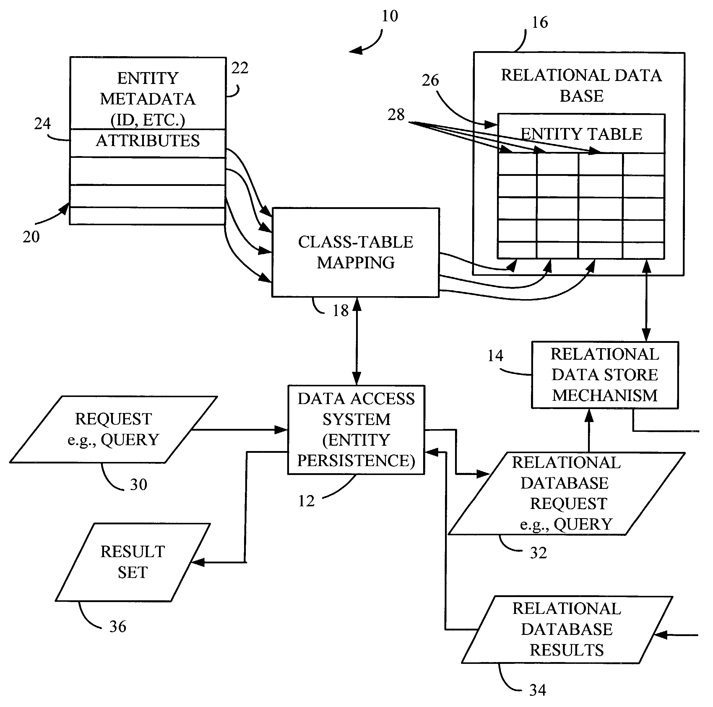
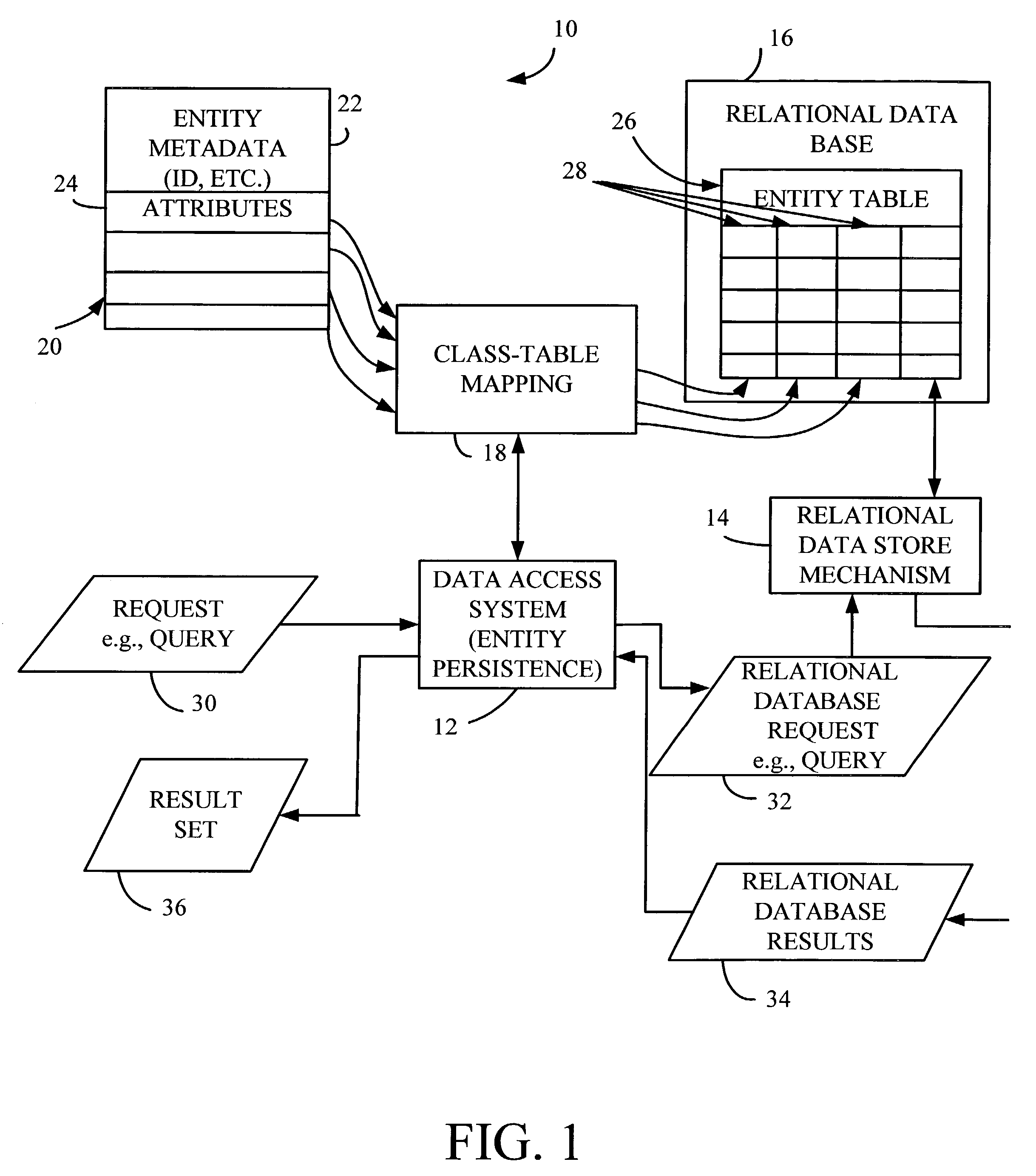
[0013]FIG. 1 is a block diagram illustrating one embodiment of a data storage and accessing system 10 in accordance with the present invention. System 10 includes data access system (or entity or object persistence system) 12, relational data store mechanism 14, relational database 16, and class-table mapping 18. System 10 is illustratively an object-relational (O-R) data storage system in which stored data can be referred to in terms of objects and their properties, rather than elements of the data base schema, such as tables and columns. FIG. 1 illustrates one mechanism for doing this.

[0014]As shown in FIG. 1, the data can be organized in terms of objects 20 (which is used interchangeably herein with the term entities). Each object illustratively includes a metadata portion 22 and a remaining attributes portion 24. The metadata portion 22 describes the object 20, while the remaining attributes 24 define further attributes of object 20, such as the data stored therein. Each of the ...


PUM


Abstract

The present invention is a method for comparing object data in an object domain with database data in a database domain. The method includes applying a first transfer function to the object data so as to generate a first transformed data. The method also includes applying a second transfer function to the database data so as to generate a second transformed data. Finally, the method includes comparing the first transformed data with the second transformed data.

Description

BACKGROUND OF THE INVENTION[0001]The present invention relates to database systems. More specifically, the present invention relates to methods for simulating data types within a database system.[0002]In conventional relational databases, all data are stored in named tables. The tables are described by their features. In other words, the rows of each table contain items of identical type, and the definitions of the columns of the table (i.e., the column names and the data types stored in the column) describe the attributes of each of the instances of the object. By identifying its name, its column names and the data types of the column contents, a table is completely described. Queries to a relational database are formulated in a query language. One such language is SQL (Structure Query Language) which is widely used in commercial relational data base systems. The data types offered by SQL can be classified as character arrays (names), numbers, and data types related to date and tim...

Claims


Application Information

Patent Timeline
04 May 2010
Publication
US7711675B2
IPC
G06F17/00; G06F15/16; G06F17/30; G06F9/45
CPC
G06F17/30607; G06F17/30595; G06F16/284; G06F16/289
Inventors
ANONSEN, STEVEN P.