Main beam fabrication procedure and system for making a main beam for warehouse framework

a fabrication procedure and main beam technology, applied in the direction of manufacturing tools, metal rolling arrangements, wire straightening devices, etc., can solve the problems of high labor and time, high cost of replacement and calibration of punching dies, and inability to adjust the pitch of punching dies of punching machines, so as to save labor and processing time and reduce the manufacturing cost of main beams

Inactive Publication Date: 2010-05-11
CHEN CHUN LIANG
View PDF3 Cites 18 Cited by
  • Summary
  • Abstract
  • Description
  • Claims
  • Application Information

AI Technical Summary

Benefits of technology

[0005]The present invention has been accomplished under the circumstances in view. It is one object of the present invention to provide a main beam fabrication procedure and system, which is adjustable to make different specifications of main be

Problems solved by technology

According to this design, the pitch of the punching dies of the punching machine is not adjustable.
Replacing the punching dies requires much time and labor.
1. For making different specifications (sizes) of main beams, different punching dies should be used. The replaceme

Method used


Image

  • Main beam fabrication procedure and system for making a main beam for warehouse framework
  • Main beam fabrication procedure and system for making a main beam for warehouse framework
  • Main beam fabrication procedure and system for making a main beam for warehouse framework

Examples


Embodiment Construction

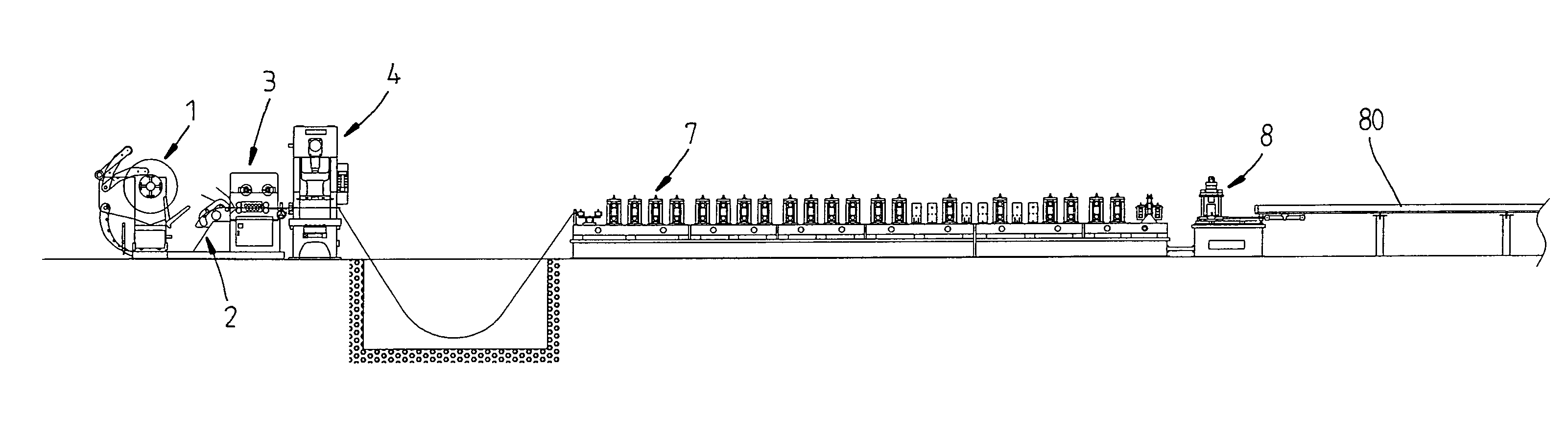
[0021]Referring to FIGS. 3-14, a main beam fabrication procedure for making a main beam for warehouse framework in accordance with the present invention comprises the steps of:

[0022](101) Material feeding (see FIGS. 13 and 14), where a feeder rack 1 feeds a plate material 2 to an auto-forwarding and flattening mechanism 3;

[0023](102) Auto-forwarding and flattening where the auto-forwarding and flattening mechanism 3 flattens the plate material 2 and then forwards the flattened plate material 2 to a punching machine 4;

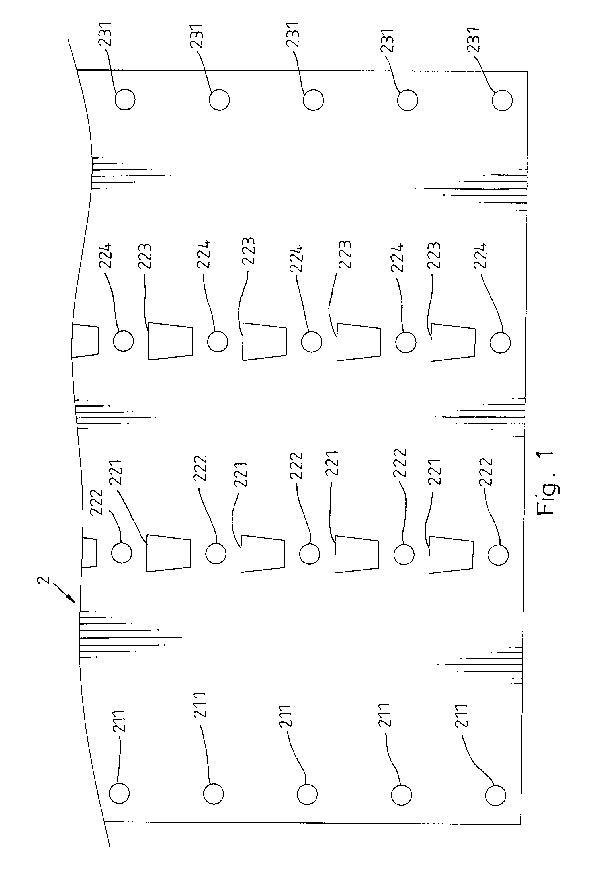
[0024](103) Punching where the punching machine 4 is operated to punch the plate material 2, forming four rows of punch holes 211, 221, 222, 223, 224, 231 on the plate material 2 (see FIGS. 1 and 4);

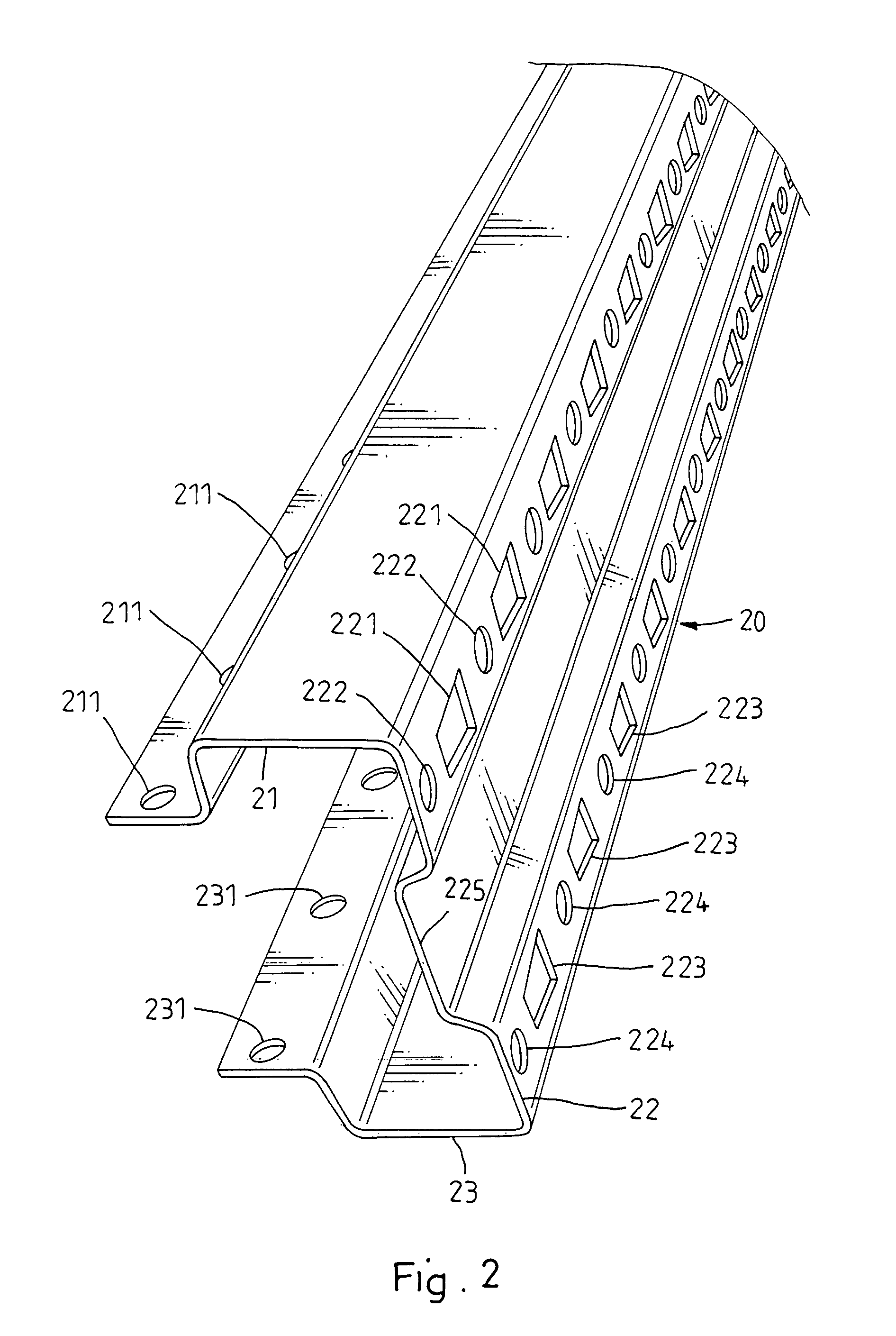
[0025](104) Roller shape-forming where a roller shape-forming machine 7 is operated to ram the punched plate material 2 into a shaped beam 20 having a front wall 22 (see FIG. 2), two curved sidewalls 21, 23, and a reinforcing groove 225 formed on the middle and extending alo...


PUM

PropertyMeasurementUnit
Timeaaaaaaaaaa

Abstract

A main beam fabrication procedure and system for making main beams for warehouse framework through feeding, auto-forwarding and flattening, punching, roller shape-forming, cutting-off and finished product collection steps, in which the punching machine comprises an upper mold holder, four upper punching dies arranged in two longitudinal rows on the bottom side of the upper mold holder and adjustable to change the transverse pitch between the two longitudinal rows of upper punching dies, a bottom mold holder, and four bottom punching dies arranged in two longitudinal rows on the top side of the bottom mold holder and adjustable to change the transverse pitch between the two longitudinal rows of bottom punching dies.

Description

BACKGROUND AND SUMMARY OF THE INVENTION[0001]The present invention relates to a main beam fabrication procedure and relates also to a main beam fabrication system, in which the punching machine has multiple pitch-adjustable punching dies for punching punch holes on the processing plate material subject to different specifications.[0002]Conventionally, the fabrication of a main beam for warehouse framework includes the steps plate material feeding, auto-forwarding and flattening, punching, roller shape-forming, cutting-off, and finished product collection. A main beam fabrication system for this main beam fabrication procedure comprises a feeder rack adapted to feed a plate material to an auto-forwarding and flattening mechanism, an auto-forwarding and flattening mechanism adapted to flatten the plate material fed by the feeder rack and then to forward the flattened plate material to a punching machine, a punching machine operable to punch the flattened plate material delivered from ...

Claims


Application Information

Patent Timeline
IPC IPC(8): B21B15/00B21B19/00B21F11/00
CPCB21D35/00B21D5/08
Inventor CHEN, CHUN-LIANG
Owner CHEN CHUN LIANG
Why Eureka
Try Eureka