Cutting head assembly for on-vehicle brake lathe

a technology of cutting head and brake disk, which is applied in the direction of portable lathes, manufacturing tools, tool holders, etc., can solve the problems of slow adjustment, inability to ensure the accuracy of machining the surface of the brake disk, and inability to adjust the angle of the cutting head

Active Publication Date: 2010-05-11
BONITA IP
View PDF25 Cites 18 Cited by
  • Summary
  • Abstract
  • Description
  • Claims
  • Application Information

AI Technical Summary

Benefits of technology

[0016]To further aid in retaining the plate on the platform as the platform is inverted, it is preferred to provide a stop element on the plate and limiting elements on the platform that are positioned to bracket the stop element and to engage the stop element to limit translation of the plate along the platform. In a preferred embodiment, the limiting elements are provided by a pair of limit pins which extend from the platform and are positioned t

Problems solved by technology

The requirement that fine threads be employed means that repositioning the plate a substantial distance along the platform will require a large number of rotations of the shaft, slowing the adjustment.
This approach also suffers in being mechanically complex, and does not appear to have been used commercially.
If these surfaces are not tightly engaged, the plate will only be stabilized at the location where it is clamped to the platform by the st

Method used


Image

  • Cutting head assembly for on-vehicle brake lathe
  • Cutting head assembly for on-vehicle brake lathe
  • Cutting head assembly for on-vehicle brake lathe

Examples


Embodiment Construction

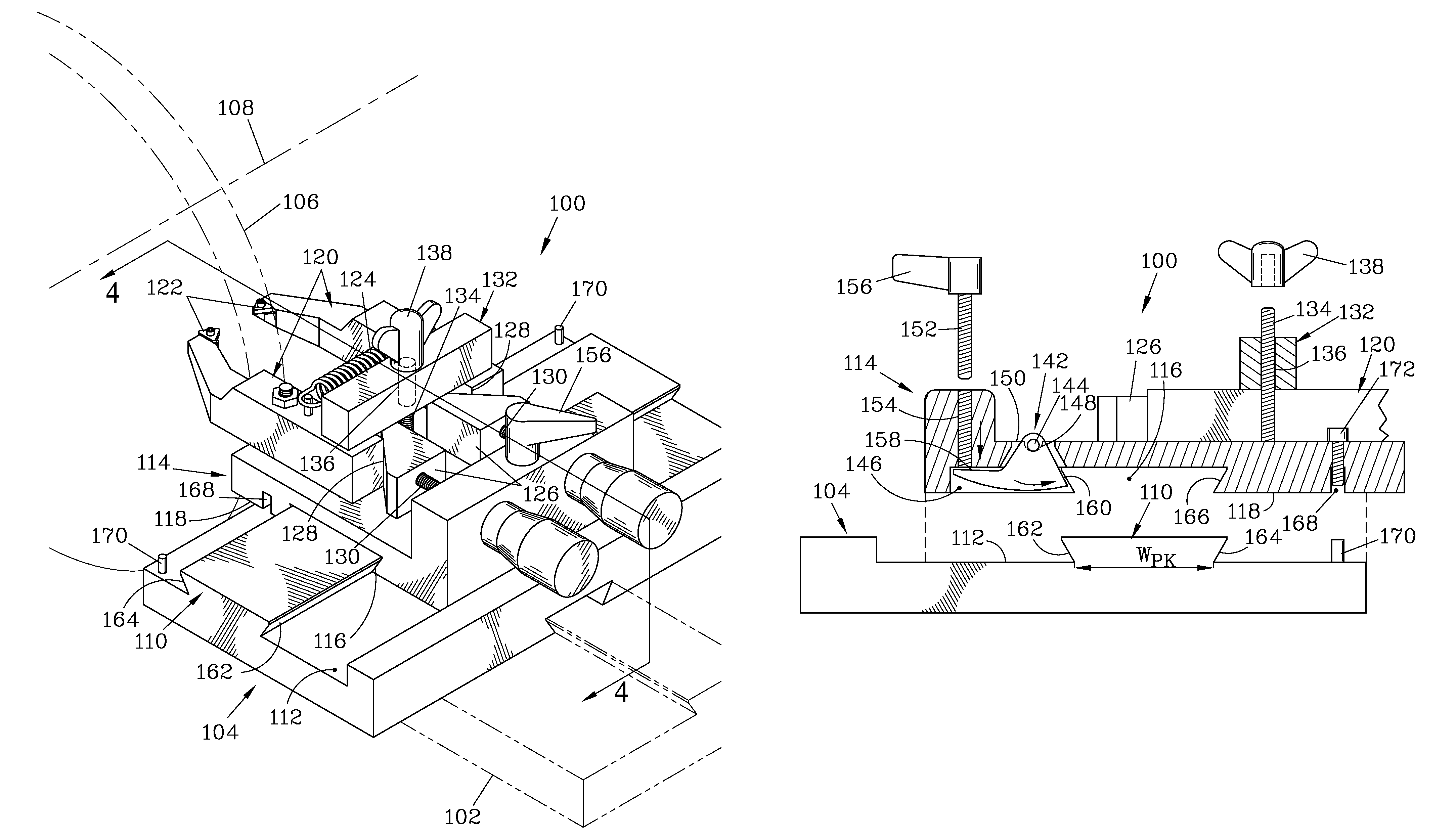
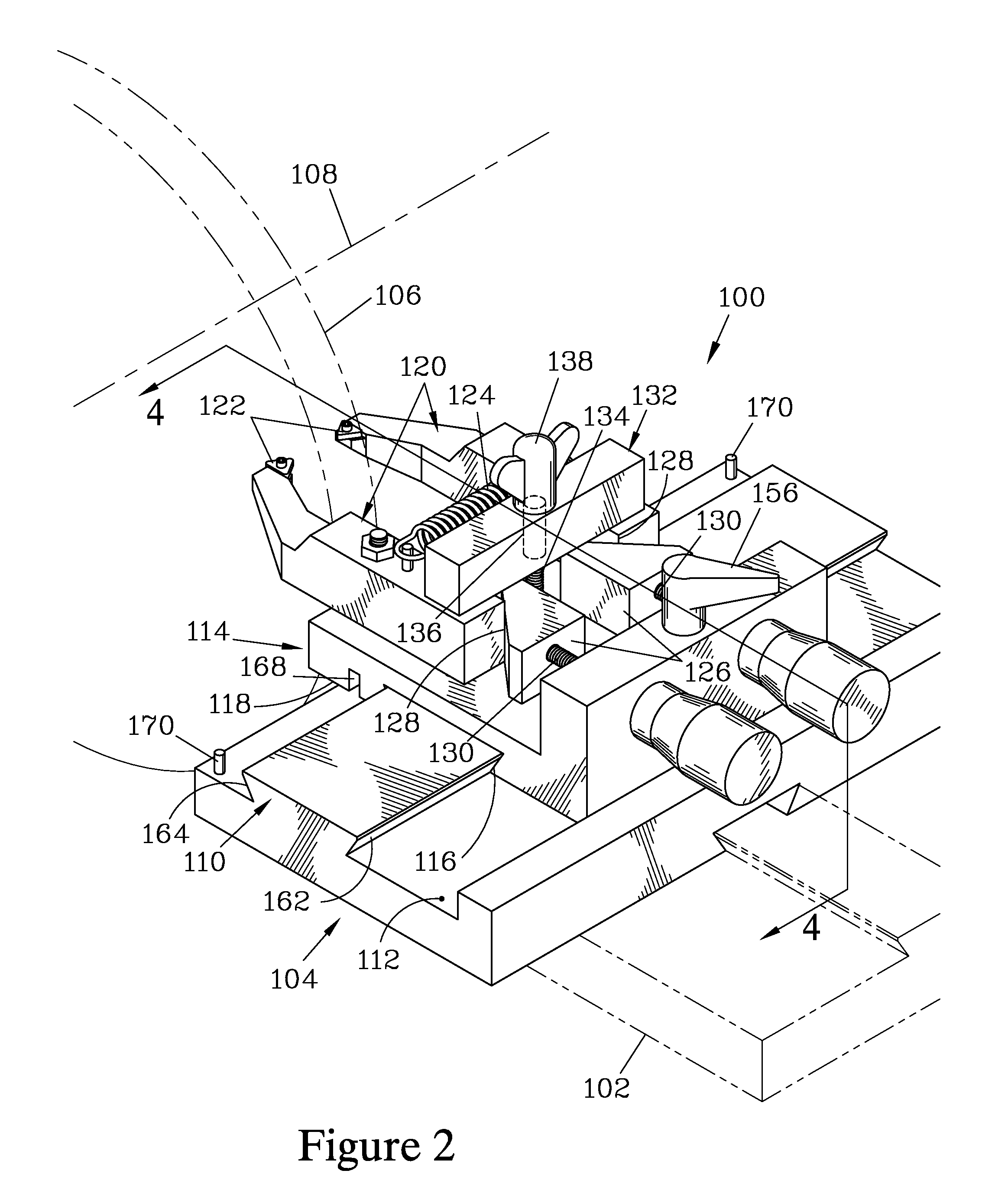
[0027]FIGS. 2 through 6 illustrate a cutting head assembly 100 which forms one embodiment of the present invention. The cutting head assembly 100 is mounted to an on-vehicle disk brake lathe having a base 102 (shown in phantom) and a platform 104. The cutting head assembly 100 is designed to machine surfaces of a brake disk 106 while the brake disk 106 it is rotated about a disk axis 108, defined as the axis of rotation of the brake disk 106. The lathe is mounted to a wheel hub (not shown) associated with the brake disk 106 and aligns itself with the disk axis 108. Thereafter, the platform 104 is driven along a path that is normal to the disk axis 108 during the machining operation to move the cutting head assembly 100 across the brake disk 106. On-vehicle disk brake lathes that mount to a wheel hub and have the ability to align themselves with the axis of rotation of the wheel hub are taught in U.S. Pat. Nos. 5,974,878; 6,050,160; 6,216,571; and continuations thereof. In the follow...


PUM

PropertyMeasurementUnit
Heightaaaaaaaaaa
Compressive stressaaaaaaaaaa

Abstract

A cutting head assembly holds a pair of tool bits for an on-vehicle brake disk lathe having a platform. The cutting head assembly has a platform key fixed to the platform and extending parallel to a brake disk axis of rotation. The cutting head assembly also has a plate having a plate keyway that slidably engages the platform key. Tool bit arms are adjustably mounted to the plate and support the tool bits. A locking structure connected to the plate locks the platform key with respect to the plate keyway, and the interaction of the locking structure with the plate and the platform key creates a compressive load between the plate and the platform as the platform key is locked with respect to the plate keyway.

Description

FIELD OF THE INVENTION[0001]The present invention relates to on-vehicle brake disk lathes, and more particularly to a cutting head assembly for such a lathe that provides improved stability and ease of adjustment.BACKGROUND OF THE INVENTION[0002]On-vehicle brake disk lathes are employed to machine the surfaces of brake disks to maintain the brakes in proper working order. The on-vehicle lathe mounts to a wheel hub of the vehicle and allows the disk associated with that hub to be machined without requiring the disk to be removed from the vehicle on which it is mounted. Such lathes have a movable cutting head assembly which serves to position a pair of tool bits that machine the surfaces of the brake disk while the brake disk is rotated about a disk axis. The tool bits are each supported on an arm, and the arms in turn are adjustably mounted to a plate. Arm adjusting knobs mounted to the plate are functionally connected to the pair of arms to cause the arms to move in response to rota...

Claims


Application Information

Patent Timeline
IPC IPC(8): B23B3/22
CPCB23B5/04B23B29/248Y10T82/21Y10T82/2585Y10T82/10Y10T82/16016
Inventor GREENWALD, CHRISTOPHER L.
Owner BONITA IP
Why Eureka
Try Eureka