Injecting molding machine having a torque detecting device

a technology of injection molding machine and torque detection, which is applied in the direction of auxillary shaping apparatus, manufacturing tools, ceramic shaping apparatus, etc., can solve the problems of disadvantageous instability of resin injection, insufficient amount to close the check ring, and excessive amount, so as to reduce the increase in metering time and accumulation of resin

Active Publication Date: 2010-05-11
FANUC LTD
View PDF12 Cites 7 Cited by
  • Summary
  • Abstract
  • Description
  • Claims
  • Application Information

AI Technical Summary

Benefits of technology

[0009]The object of the present invention is to provide an injection molding machine that performs control so as to rotate the screw in reverse by the optimal amount for reliably closing the check ring of the screw.
[0019]In the above configuration, the injection molding machine according to the present invention can reliably close the check ring even if the resin viscosity and other conditions vary. It is also possible to minimize the increase in metering time and accumulation of resin due to reverse rotation of the screw. In addition, if the amount of reverse rotation of the screw necessary to close the check ring is displayed on the screen, the operator can use the displayed value as a guide for setting an amount of reverse rotation of the screw.

Problems solved by technology

Therefore, if the amount of reverse rotation at injection is set as described in the above conventional art, the amount may be not enough to close the check ring completely, or the amount may be excessive, depending on the resin and molding conditions.
If the amount of reverse rotation of the screw is not enough to close the check ring completely, the amount of resin injected becomes disadvantageously unstable.
If the amount of reverse rotation is excessive, an extra amount of resin is fed behind the screw, causing problems of increased metering time and accumulation of resin.

Method used


Image

  • Injecting molding machine having a torque detecting device
  • Injecting molding machine having a torque detecting device
  • Injecting molding machine having a torque detecting device

Examples


Embodiment Construction

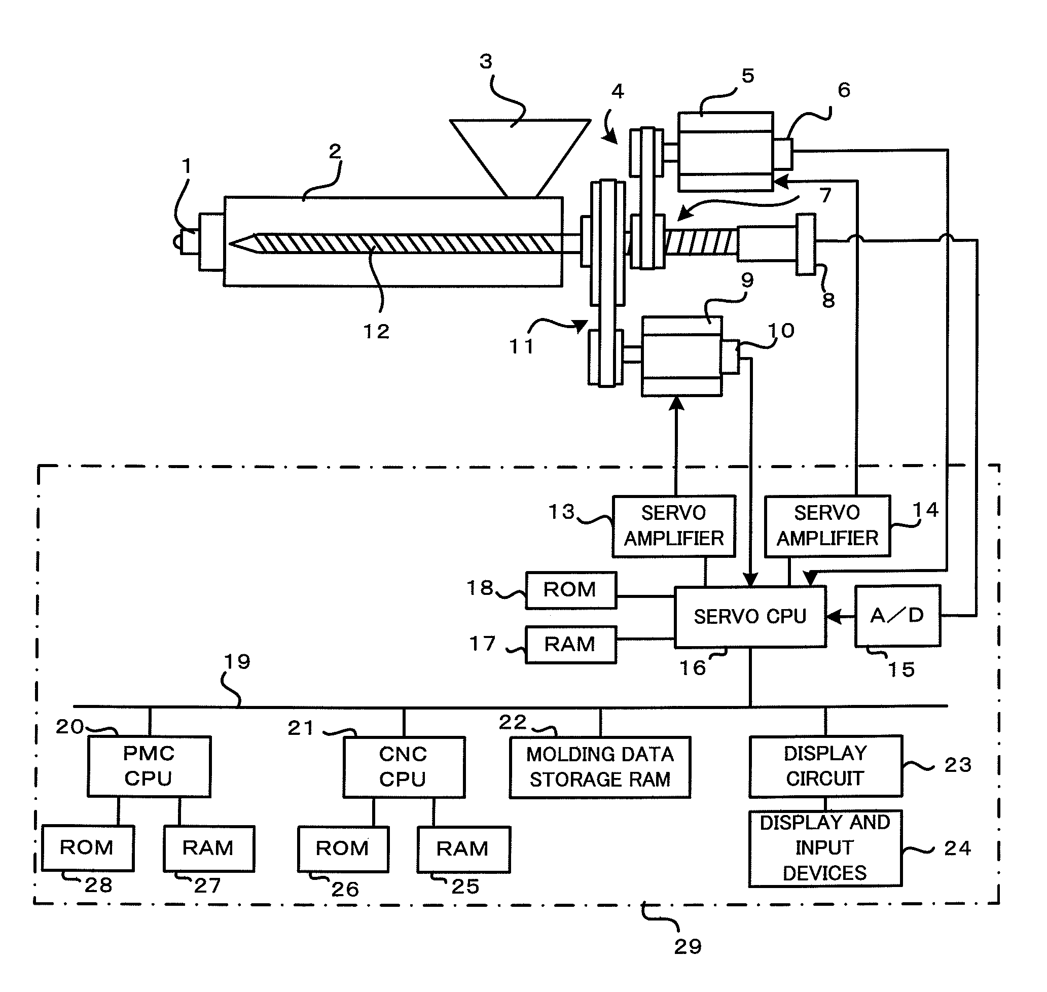
[0029]FIG. 1 is a block diagram showing the main sections of an injection molding machine in an embodiment of the present invention.

[0030]An injection cylinder 2, in which a screw 12 is inserted, has a nozzle 1 at its front end. The injection cylinder 2 has a hopper 3 near its rear end, through which resin pellets are supplied to the injection cylinder 2. The screw 12 is rotated when driven by a screw rotating servo motor 9 through a transmission mechanism 11. The screw 12 is also axially driven to control injection and back pressure by an injection servo motor 5 through a transmission mechanism 4 and a conversion mechanism 7 such as a ball screw and nut that converts rotational motion into rectilinear motion.

[0031]The injection servo motor 5 and screw rotating servo motor 9 are equipped with respective position / speed detecting devices 6, 10 for detecting their rotational position and speed. The position / speed detecting devices 6, 10 are used to detect the rotational position and sp...


PUM

PropertyMeasurementUnit
torqueaaaaaaaaaa
distanceaaaaaaaaaa
timeaaaaaaaaaa

Abstract

When a screw equipped with a check ring is moved forward, torque acting on the screw is detected, and whether the check ring is closed is determined on the basis of the detected torque. The screw is rotated in reverse when the check ring is determined not to be closed, and the reverse rotation of the screw is stopped when the check ring is determined to be closed. The reverse rotation of the screw is thereby controlled so that the screw is rotated in reverse by an optimal amount for reliably closing the check ring.

Description

RELATED APPLICATIONS[0001]The present application is based on, and claims priority from, Japanese Application Number 2007-281981 filed Oct. 30, 2007 and Japanese Application Number 2007-186032 filed Jul. 17, 2007, the disclosure of which is hereby incorporated by reference herein in its entirety.BACKGROUND OF THE INVENTION[0002]1. Field of the Invention[0003]The present invention relates to an injection molding machine, and more particularly to an injection molding machine that determines whether a check ring is closed or not during forward movement of a screw and rotates the screw in reverse by an amount necessary to close the check ring.[0004]2. Description of the Related Art[0005]In a known technique described in, for example, Japanese Patent Application Laid-Open No. 62-060621, the check ring in an injection molding machine is closed by rotating the screw in reverse (or in the direction reverse to the direction of the screw during metering process) at the start of injection. The...

Claims


Application Information

Patent Timeline
Patent Type & Authority Patents(United States)
IPC IPC(8): B29C45/76
CPCB29C45/52B29C45/76B29C2945/76545B29C2945/76187B29C2945/76367B29C2945/7602
Inventor MARUYAMA, JUNPEITAKATSUGI, SATOSHI
Owner FANUC LTD
Why Eureka
Try Eureka