Transfer box with crown teeth

a transfer box and crown technology, applied in the field of transfer boxes, can solve the problem of small number of parts

Inactive Publication Date: 2010-05-11
GKN DRIVELINE INT GMBH
View PDF14 Cites 8 Cited by
  • Summary
  • Abstract
  • Description
  • Claims
  • Application Information

AI Technical Summary

Benefits of technology

[0006]According to a particularly advantageous embodiment, a gearwheel or sprocket wheel for driving the second output shaft via a gearwheel stage or chain drive is integrally connected to the second side gear. Again, the number of parts is reduced.
[0009]According to a second embodiment it is possible for the side gears to support each other axially, with a carrier being connected to one side gear which carrier extends over the other side gear and via which the other side gear is axially supported on the first mentioned side gear. An axial bearing or friction discs can be provided between the carrier and the outside of the second side gear. An axial bearing generates the effect of an open differential, whereas the friction discs can generate a friction moment which inhibits the differential effect. The axial forces generated by the tooth forces are compensated for as inner forces via the carrier. The tooth play can be set by using discs at the axial bearing or by accurately positioning the carrier on the other sideshaft gear prior to connecting the two parts to one another. The element referred to as a carrier in this context and serving to support the two side gears relative to one another can be cost-effectively produced in the form of a deep-drawn metal part.
[0012]The above-described invention provides a simple differential assembly wherein drive is effected from the center via the carrier spider member of the differential gears. The axial forces acting on the side gears can be supported directly on the housing if a carrier in the conventional sense has not been provided.

Problems solved by technology

The differential gears supported with radial axes between the side gears are directly supported on the input shaft, which results in a very small number of parts.

Method used


Image

  • Transfer box with crown teeth
  • Transfer box with crown teeth
  • Transfer box with crown teeth

Examples


Embodiment Construction

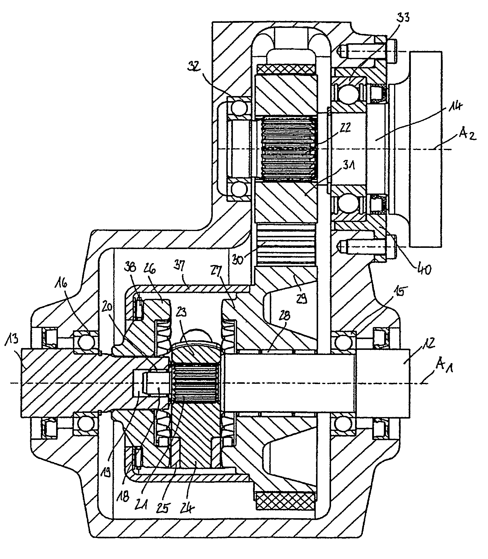
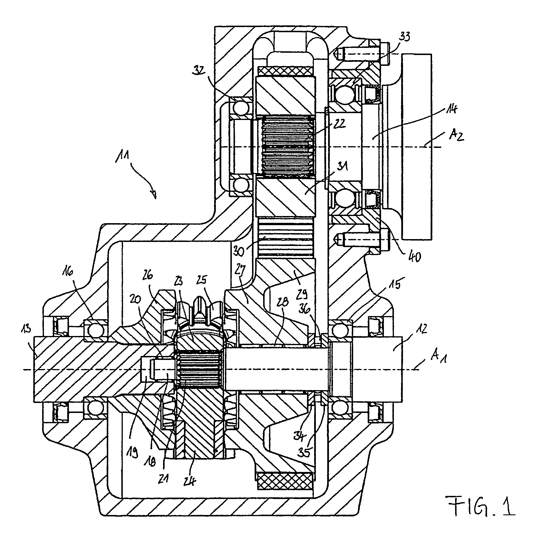
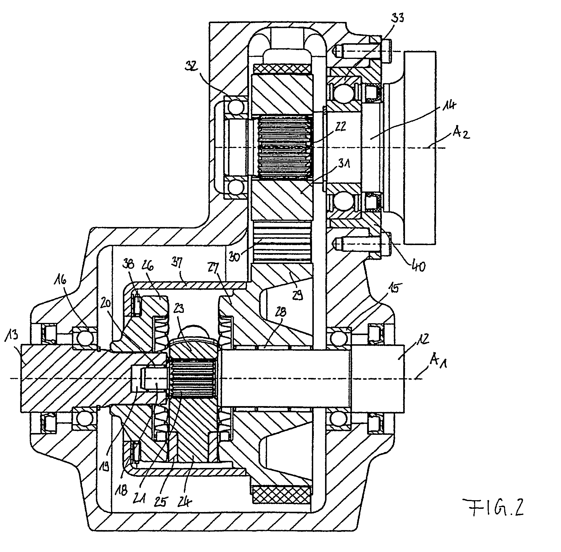
[0018]FIGS. 1 to 3 will initially be described jointly to the extent that their respective designs correspond to one another.

[0019]They each show an inventive transfer box whose housing 11 is shown in principle only and which can be divided in the drawing plane for example. An input shaft 12 and a first output shaft 13 are arranged coaxially relative to one another on a first axis Al. A second output shaft 14 is rotatably arranged on a second axis A2 which extends parallel to the axis Al. The input shaft 12 is supported via a ball bearing 15 in a second housing aperture. A journal projection 18 engaging a central recess 19 in the first output shaft 13 is provided at the input shaft 12, with the journal projection 18 being supported via a needle bearing 20 in the recess 19. The input shaft 12 comprises shaft teeth 21 which adjoin the journal projection 18 and on to which there is slid a spider member 23 which comprises corresponding inner teeth and which is provided with three circum...


PUM


Abstract

A transfer box with a housing, an input shaft, a first output shaft extending coaxially relative to said input shaft, and a second output shaft extending parallel to said two shafts, as well as with a differential gear assembly arranged between said shafts, wherein the input shaft carries a cross member with a plurality of radial bearing arms for the differential gears, wherein a first side gear is connected in a rotationally fast way to the first output shaft and wherein a second side gear is rotatably supported on the input shaft and drives the second output shaft, wherein the differential gears are spur gears and the side gears crown gears and wherein the teeth of the differential gears engage the teeth of the side gears.

Description

TECHNICAL FIELD[0001]The invention relates to a transfer box with a housing, an input shaft, a first output shaft extending coaxially relative to said input shaft, and a second output shaft extending parallel to said first output shaft and said input shaft, as well as with a differential gear assembly arranged between said shafts.BACKGROUND[0002]In vehicles with two permanently driven axles, transfer boxes of said type, on the one hand, serve to drive a rear axle through a first output shaft and, on the other hand, they serve to drive a front axle through a second output shaft which, as a rule, is offset relative to and extends parallel relative to the input shaft. The torque can be uniformly distributed between the output shafts by the differential gear assembly or a biased torque load can be applied to one of the output shafts.[0003]The torque distribution in transfer boxes of this type is commonly effected by planetary gear differential assemblies for dividing the torque between ...

Claims


Application Information

Patent Timeline
Patent Type & Authority Patents(United States)
IPC IPC(8): F16H37/02F16H48/06B60K17/346F16H37/08F16H48/10
CPCB60K17/346F16H37/0813F16H48/10F16H2048/102
Inventor GASSMANN, THEODORFUCHS, HEINZWILLI
Owner GKN DRIVELINE INT GMBH
Why Eureka
Try Eureka