Polarless surface mounting light emitting diode

a technology of light-emitting diodes and polarized surfaces, which is applied in the field of diodes, can solve the problems of increased complexity in circuit design, increased cost, and the inability of diodes to opera

Active Publication Date: 2010-05-11
LIN PETER P W
View PDF5 Cites 824 Cited by
  • Summary
  • Abstract
  • Description
  • Claims
  • Application Information

AI Technical Summary

Problems solved by technology

If the connect is incorrect, the diode can not operate.
As a result, not only the complexity in circuit design is increased, but also the cost is also increased.

Method used


Image

  • Polarless surface mounting light emitting diode
  • Polarless surface mounting light emitting diode
  • Polarless surface mounting light emitting diode

Examples


Embodiment Construction

[0011]In order that those skilled in the art can further understand the present invention, a description will be provided in the following in details. However, these descriptions and the appended drawings are only used to cause those skilled in the art to understand the objects, features, and characteristics of the present invention, but not to be used to confine the scope and spirit of the present invention defined in the appended claims.

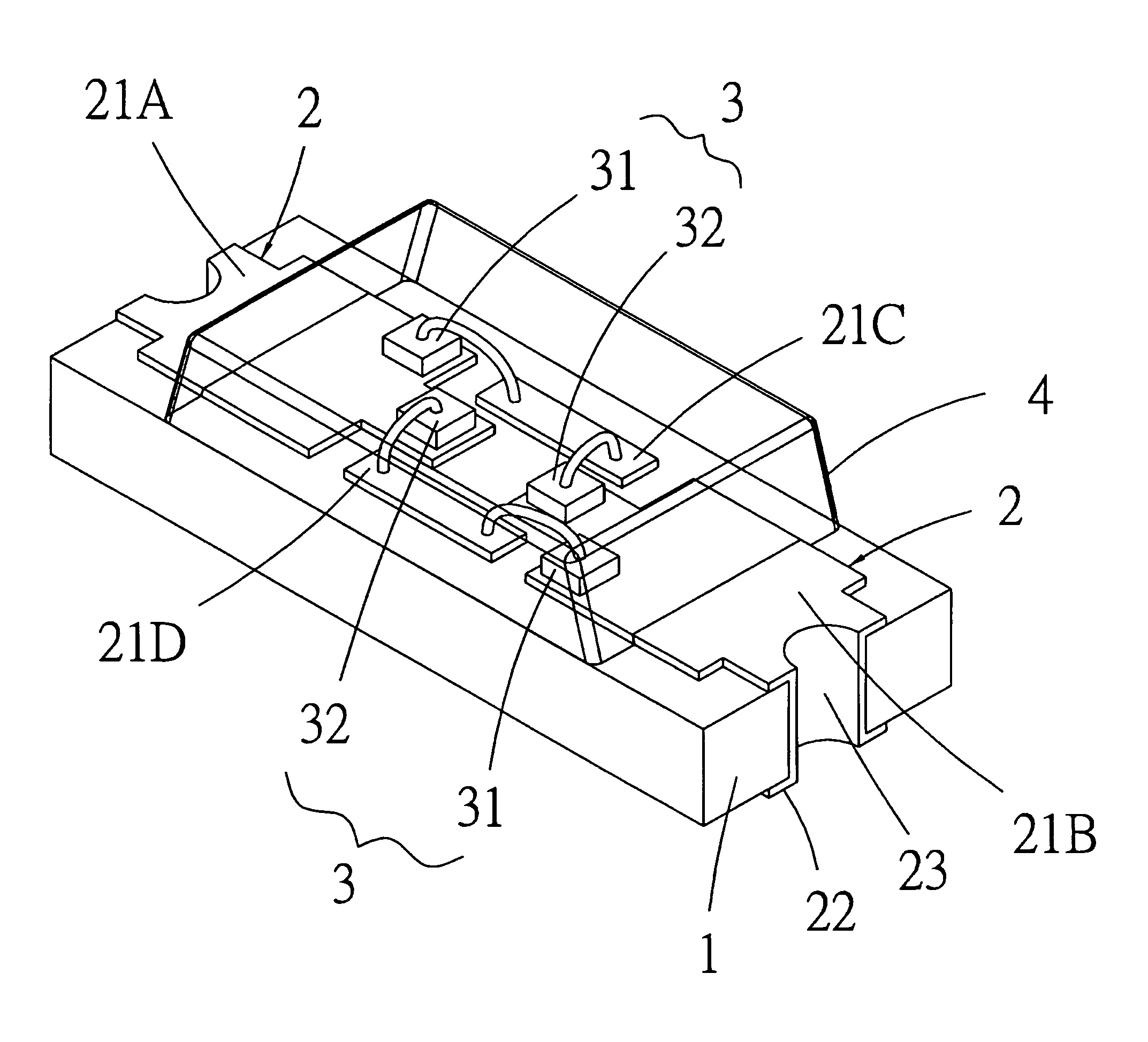
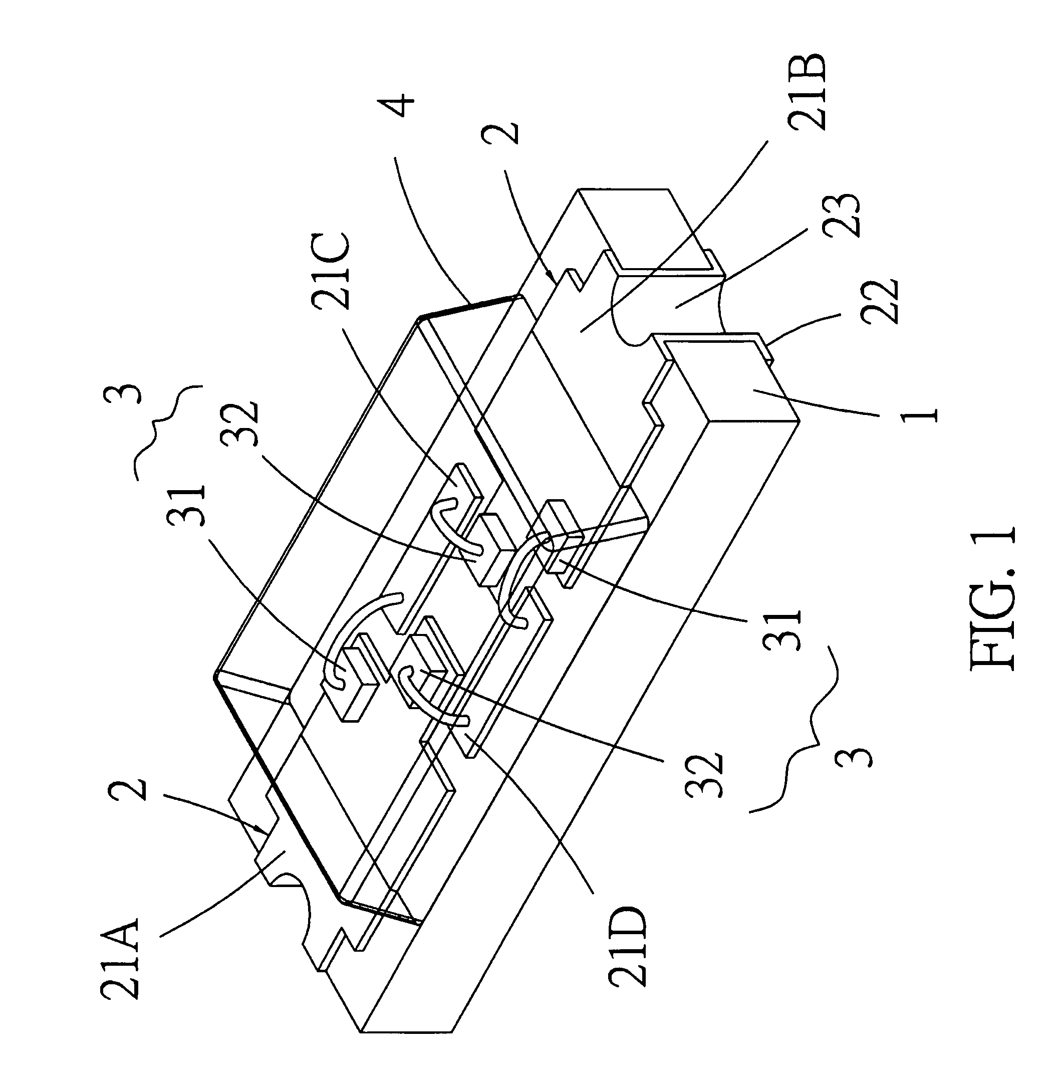
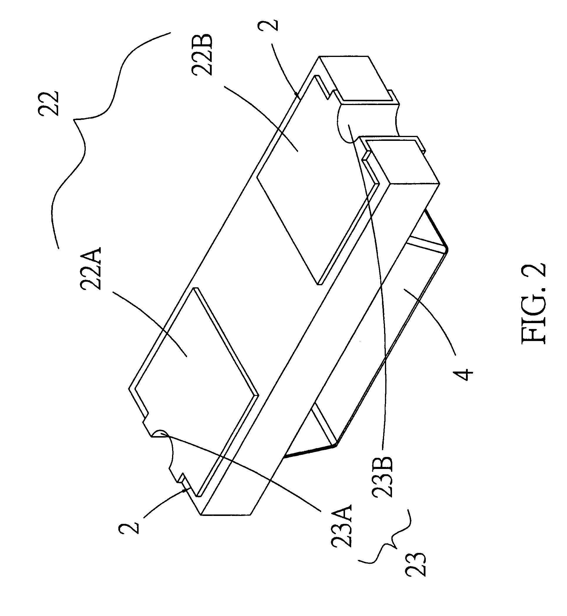
[0012]Referring to FIGS. 1 and 2, the polarless surface mounting light emitting diode of the present invention is illustrated. The structure of the present invention will be described herein.

[0013]A substrate 1 has two surfaces which are adhered with copper foil metal thin films by thermal pressing. An upper surface of the substrate 1 is etched with four independent metal thin film block. A lower surface of the substrate 1 is formed with two independent metal thin film block. Two ends of the substrate 1 are formed with respective left electroplated...


PUM


Abstract

A polarless surface mounting light emitting diode comprises a substrate; an upper surface of the substrate being etched with four independent metal thin film blocks; a lower surface of the substrate being formed with two independent metal thin film blocks; two ends of the substrate being formed with electroplated through holes; a plurality of metal thin films adhered upon the upper and lower surfaces of the substrate; two light emitting assemblies, each light emitting assembly being formed by a chip resistor and a chip light emitting diode; and a package layer. The connection of the polarless surface mounting light emitting diode of the present invention is not limited by the polarity. Any end of the polarless surface mounting light emitting diode can be connected to positive electrode or negative electrode.

Description

FIELD OF THE INVENTION[0001]The present invention relates to diodes, and particularly to a polarless surface mounting light emitting diode, wherein the connection of the polarless surface mounting light emitting diode of the present invention is not limited by the polarity. Any end of the polarless surface mounting light emitting diode can be connected to positive electrode or negative electrode.BACKGROUND OF THE INVENTION[0002]In a prior art surface mounting light emitting diode, one end of the diode is a P type junction surface and another end thereof is an N type junction surface. The P type junction surface is connected to a positive electrode and the N type junction surface is connected to a negative electrode. The diode is operated by positive bias so that the surface mounting light emitting diode can light up. If the P type junction surface is connected to a negative electrode and the N type junction surface is connected to a negative electrode, then the diode is negative bia...

Claims


Application Information

Patent Timeline
Patent Type & Authority Patents(United States)
IPC IPC(8): H01L29/267
CPCH01L25/0753H01L25/167H01L2224/48091H01L2224/48227H01L2224/49113H01L2924/00014
Inventor LIN, PETER P. W.
Owner LIN PETER P W
Why Eureka
Try Eureka