Check patentability & draft patents in minutes with Patsnap Eureka AI!

Load control module

a load control and module technology, applied in the direction of switch power arrangement, contact mechanism, lighting and heating apparatus, etc., can solve the problems of limited circuit performance of general illumination apparatus or electrical equipment under control of the switch, and the conventional load control module cannot meet the requirements of convenien

Inactive Publication Date: 2010-05-11
GE INVESTMENT
View PDF7 Cites 10 Cited by
  • Summary
  • Abstract
  • Description
  • Claims
  • Application Information

AI Technical Summary

Benefits of technology

The load control module allows electrical equipment to perform diversified control functions, such as adjusting brightness or temperature, by maintaining operation and adjusting control voltage levels even when the switch is off, enhancing the convenience and functionality of electrical devices.

Problems solved by technology

In other words, circuit performance of a general illumination apparatus or a electrical equipment under control of the switch and the conventional load control module is limited and cannot match a requirement of convenience.

Method used


Image

  • Load control module
  • Load control module
  • Load control module

Examples


Embodiment Construction

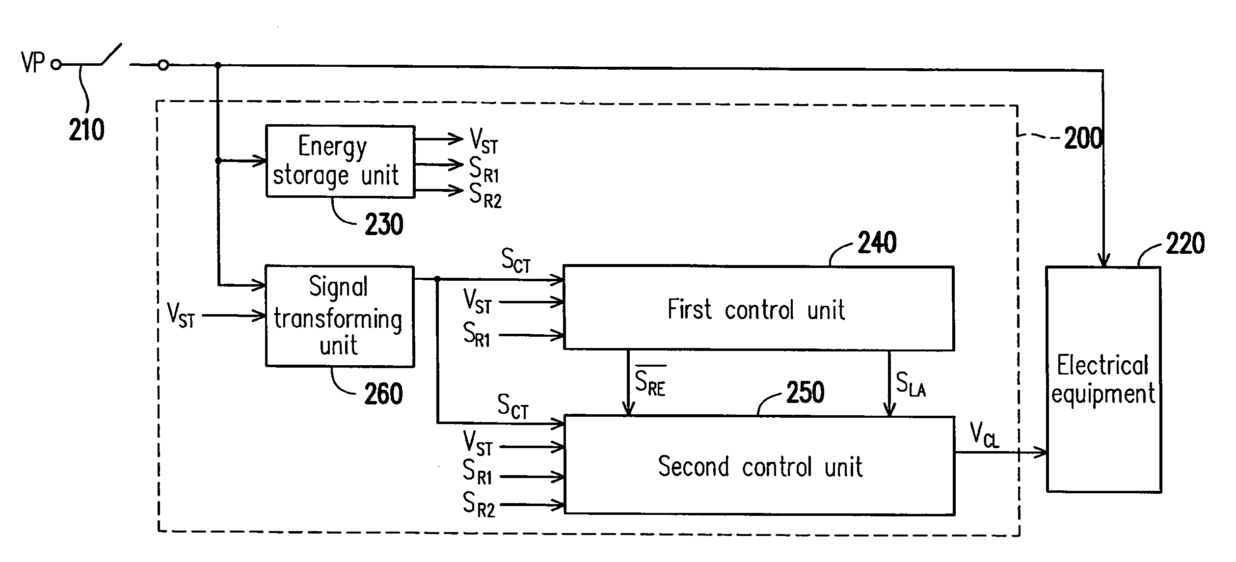
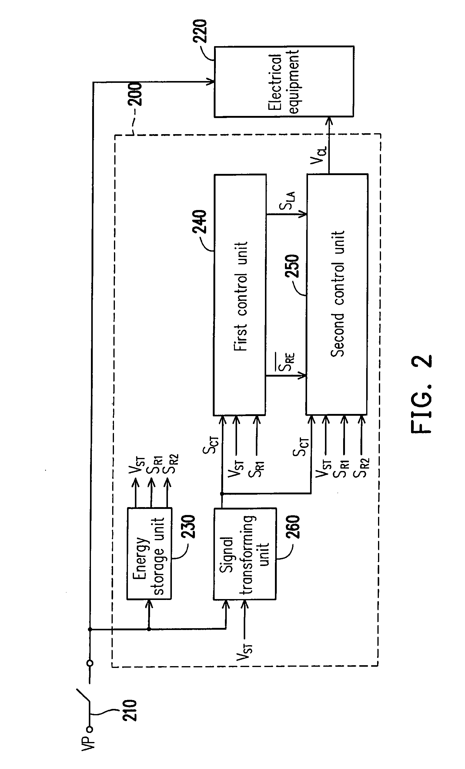
[0025]FIG. 2 is a circuit block diagram of a load control module according to an embodiment of the present invention. The load control module 200 is suitable for an electrical equipment 220 driven by an operation of a switch 210. Moreover, the load control module 200 includes an energy storage unit 230, a first control unit 240, a second control unit 250 and a signal transforming unit 260. The energy storage unit 230 is coupled to the switch 210, the first control unit 240, the second control unit 250 and the signal transforming unit 260. The first control unit 240 is coupled to the signal transforming unit 260, and the second control unit 250 is coupled to the first control unit 240 and the signal transforming unit 260.

[0026]FIG. 3 is a timing diagram of waveforms according to the embodiment of FIG. 2. Referring to FIG. 2 and FIG. 3, the switch 210 switches in response to a switching signal S31. For example, when the level of the switching signal S31 is switched to a first level L1...


PUM


Abstract

A load control module suitable for an electrical equipments driven by an operation of a switch is disclosed. The load control module includes an energy storage unit, a signal transforming unit, a first control unit and a second control unit. The energy storage unit still outputs a reserved voltage for a predetermined time during the switch is turned off. The signal transforming unit and the first and the second control unit are driven by the reserved voltage. With a different switching speed of the switch, the second control unit may operate in coordination with the actions of the signal transforming unit and the first control unit to regulate a level of the control voltage, or maintain the level of the control voltage in a current state. The electrical equipments may perform diversified control functions under control of the load control module operated in coordination with an operation of the switch.

Description

CROSS-REFERENCE TO RELATED APPLICATION[0001]This application claims the priority benefit of Chinese application serial no. 200710148134.8, filed on Aug. 28, 2007. All disclosure of the Chinese application is incorporated herein by reference.BACKGROUND OF THE INVENTION[0002]1. Field of the Invention[0003]The present invention relates to a load control module. More particularly, the present invention relates to a load control module allowing an electrical equipment to perform diversified control functions.[0004]2. Description of Related Art[0005]With discovering of electricity by an American Franklin in the 18th century, civilization of human beings advanced a big step. In today's world, application of the electricity not only contributes productions of social materials, but also widely infiltrates human life in all dimensions. For example, the electrical equipments used in our daily life, such as illumination apparatus, air conditioner, electric fans, food heater . . . etc. are all d...

Claims


Application Information

Patent Timeline
Patent Type & Authority Patents(United States)
IPC IPC(8): H01H33/59H05B44/00
CPCH05B33/0845H05B37/02H05B41/40H05B41/39H05B39/04H05B47/10H05B47/185
Inventor TSAI, WEN-KUEIWANG, CHUN-CHIEN
Owner GE INVESTMENT
Features
  • R&D
  • Intellectual Property
  • Life Sciences
  • Materials
  • Tech Scout
  • Unparalleled Data Quality
  • Higher Quality Content
  • 60% Fewer Hallucinations
Learn More