
Battery charging arrangement for unmanned aerial vehicle utilizing the electromagnetic field associated with utility power lines to generate power to inductively charge energy supplies

a technology of electromagnetic field and electric power supply, which is applied in the direction of charging stations, batteries/cells, transportation and packaging, etc., can solve the problems of inherent trade-off between duration and useful payload, electrically powered uav flight times are typically limited to less than one hour, and the range and duration of electric powered uavs are limited

Inactive Publication Date: 2010-05-11
THE UNITED STATES OF AMERICA AS REPRESENTED BY THE SECRETARY OF THE NAVY
View PDF6 Cites 349 Cited by
  • Summary
  • Abstract
  • Description
  • Claims
  • Application Information

AI Technical Summary

Problems solved by technology

Currently, electrically powered UAVs are limited in range and duration by the size and weight of the batteries which they can carry.
Consequently, there is an inherent tradeoff between duration and useful payload.
Because of these constraints, the flight times of electrically powered UAVs are typically limited to less than one hour.
Additionally, the distance traveled from a base location is also limited.
Also of concern is that UAV batteries slowly lose their energy even when they are completely powered down.
This limits the ability of UAVs to shut down for extended periods of time and then be useful again if the vehicle cannot be recharged.

Method used


Image

  • Battery charging arrangement for unmanned aerial vehicle utilizing the electromagnetic field associated with utility power lines to generate power to inductively charge energy supplies
  • Battery charging arrangement for unmanned aerial vehicle utilizing the electromagnetic field associated with utility power lines to generate power to inductively charge energy supplies
  • Battery charging arrangement for unmanned aerial vehicle utilizing the electromagnetic field associated with utility power lines to generate power to inductively charge energy supplies

Examples


Embodiment Construction

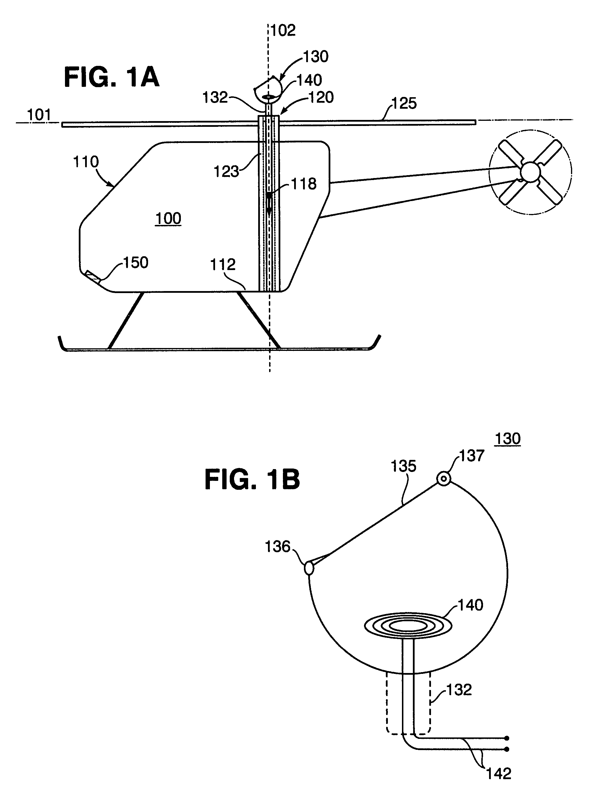
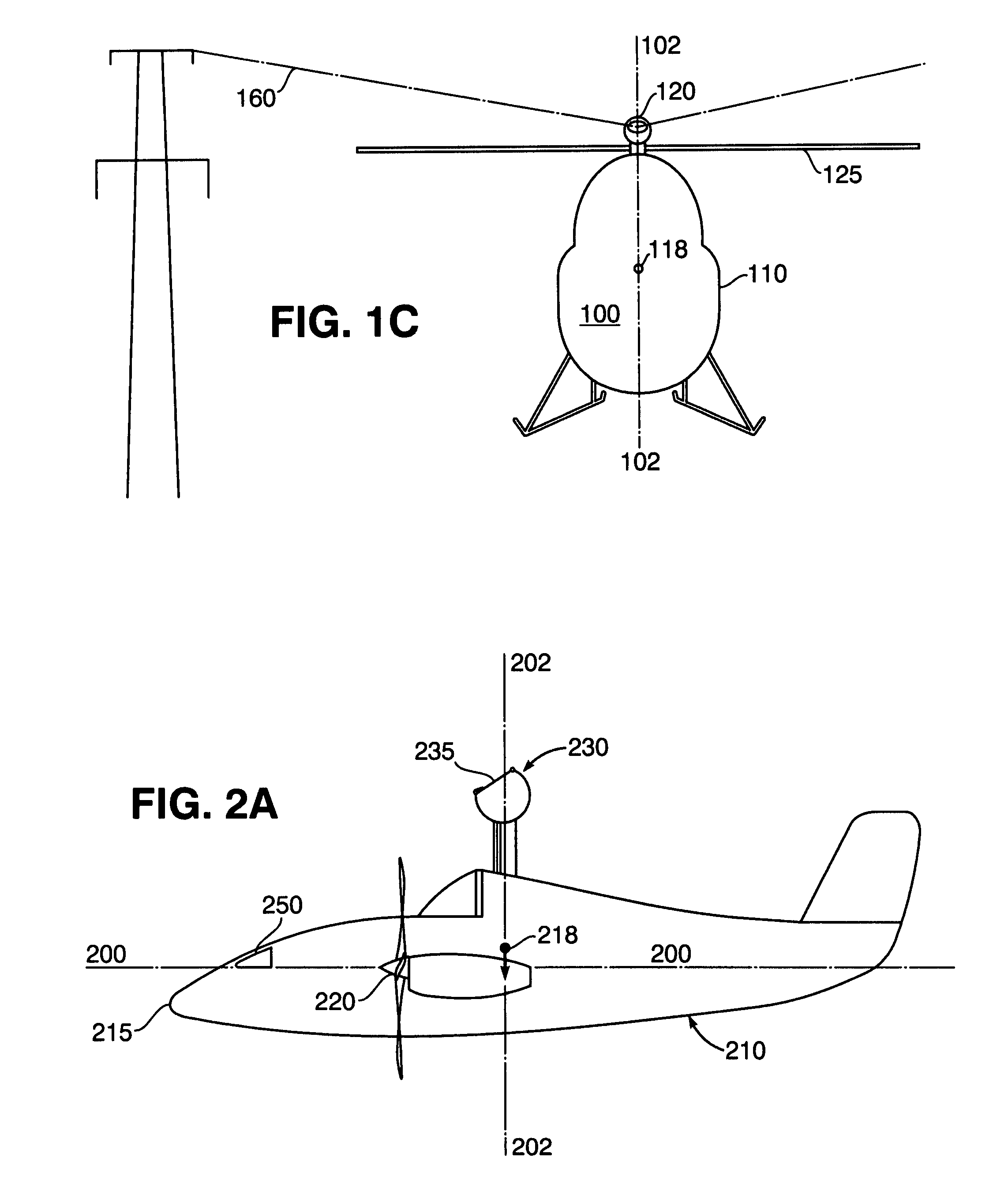
[0017]FIG. 1A is a perspective view of an unmanned aerial vehicle (UAV) 100 in accordance with an embodiment of the present invention. The UAV 100 is a vertical takeoff vehicle, and as illustrated in FIG. 1A, the UAV is in an upright orientation. The UAV 100 has a horizontal reference line 101 and a vertical reference line 102. In the upright orientation, the horizontal reference line 101 has a substantially horizontal orientation, and the vertical reference line 102 has a substantially vertical orientation. When the UAV 100 is in motion, the horizontal and vertical reference lines may assume other orientations.

[0018]In this embodiment, the UAV 100 has a vehicle body 110 with a base portion 112. The UAV 100 is powered by a propulsion system, shown generally at 120. The propulsion system, which is preferably electrically powered, includes a hollow rotor shaft 123 and one or more horizontal rotors 125 attached to the hollow rotor shaft 123. As illustrated, the horizontal reference lin...


PUM


Abstract

A method and apparatus for charging energy supplies in an unmanned aerial vehicle (UAV). The present invention relates to a UAV that comprises an inductive charging device that utilizes the electromagnetic field emanated by overhead / utility power lines, to charge the energy supplies. The UAV also includes a releasable latch for holding power lines to allow for the perching of the UAV on power lines during the charging process. The latch and the inductive charging device may be provided on a single device, a battery augmentation trap (BAT). The UAV may be perched in an upright orientation to allow for takeoff after the charging of energy supplies on the power line.

Description

STATEMENT OF GOVERNMENT INTEREST[0001]The invention described herein may be manufactured and used by or for the Government of the United States of America for governmental purposes without the payment of any royalties thereon or therefore.FIELD OF THE INVENTION[0002]The present invention relates generally to a method and apparatus for charging energy supplies in an unmanned aerial vehicle (UAV), more particularly, the present invention relates to a UAV that comprises an inductive charging device that generates a charging current by utilizing the electromagnetic field emanated by overhead / utility power lines, the UAV also including a latch for perching on the utility power lines during the charging process.BACKGROUND OF THE INVENTION[0003]An unmanned aerial vehicle, commonly referred to a UAV, is an aircraft with no onboard pilot. UAVs may be expendable or recoverable and may fly autonomously or remotely. In autonomous applications, the vehicle is either pre-programmed with flight pl...

Claims


Application Information

Patent Timeline
IPC IPC(8): H02J7/00
CPCB60L11/002B60L11/1801B60L11/182B64C39/024B60L2200/10B60L2200/20Y02T90/122B64C2201/042B64C2201/063Y02T10/7005Y02T90/14B60L2260/32Y02T10/7072B60L50/53B60L50/90B60L53/126Y02T10/70B64U50/34B64U10/14B64U10/17B64U80/25Y02T90/12B64U50/19
Inventor SILBERG, ERIC J.MILGRAM, JUDAH H.
Owner THE UNITED STATES OF AMERICA AS REPRESENTED BY THE SECRETARY OF THE NAVY
Learn More