Switching power supply circuitry
a power supply circuit and circuit technology, applied in the direction of process and machine control, pulse technique, instruments, etc., can solve the problems of overshoot on the output voltage vout, load b>10/b>, microcomputers, etc., to achieve positive start of the switching power supply circuitry, reduce power consumption, and stable operation of the control circui
- Summary
- Abstract
- Description
- Claims
- Application Information
AI Technical Summary
Benefits of technology
Problems solved by technology
Method used
Image
Examples
embodiment 1
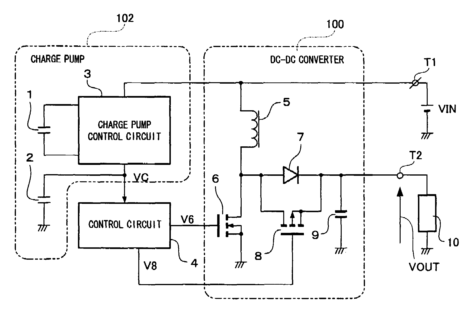
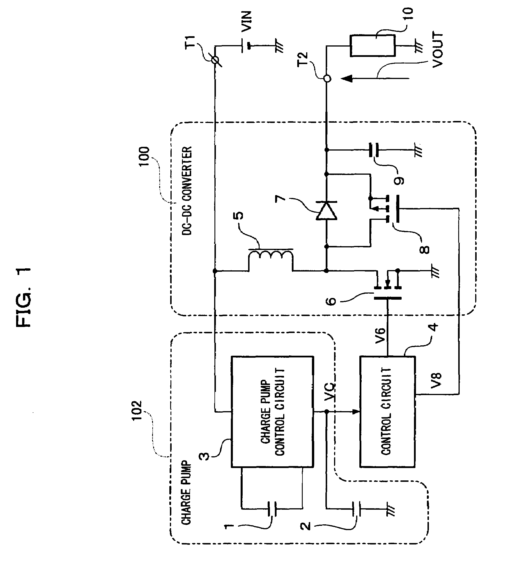
[0044]FIGS. 1 and 3 show switching power supply circuitry according to Embodiment 1 of the present invention.
[0045]In the switching power supply circuitry, an input voltage VIN applied to an input terminal T1 is outputted as an output voltage VOUT to an output terminal T2 through a DC-DC converter 100 acting as a step-up converter. In the DC-DC converter 100, a step-up converter is made up of a choke coil 5 having one end connected to the input terminal T1, a main switch 6 including an N-channel MOS transistor, a rectifier diode 7, a rectifier switch 8, and an output smoothing capacitor 9. To be specific, the anode of the rectifier diode 7, the drain of the main switch 6, and the drain of the rectifier switch 8 are connected to the other end of the choke coil 5 and the source of the main switch 6 is grounded. The output of the rectifier diode 7 and the rectifier switch 8 is smoothed by the output smoothing capacitor 9 and supply to a load 10 connected to the output terminal T2.
[0046...
embodiment 2
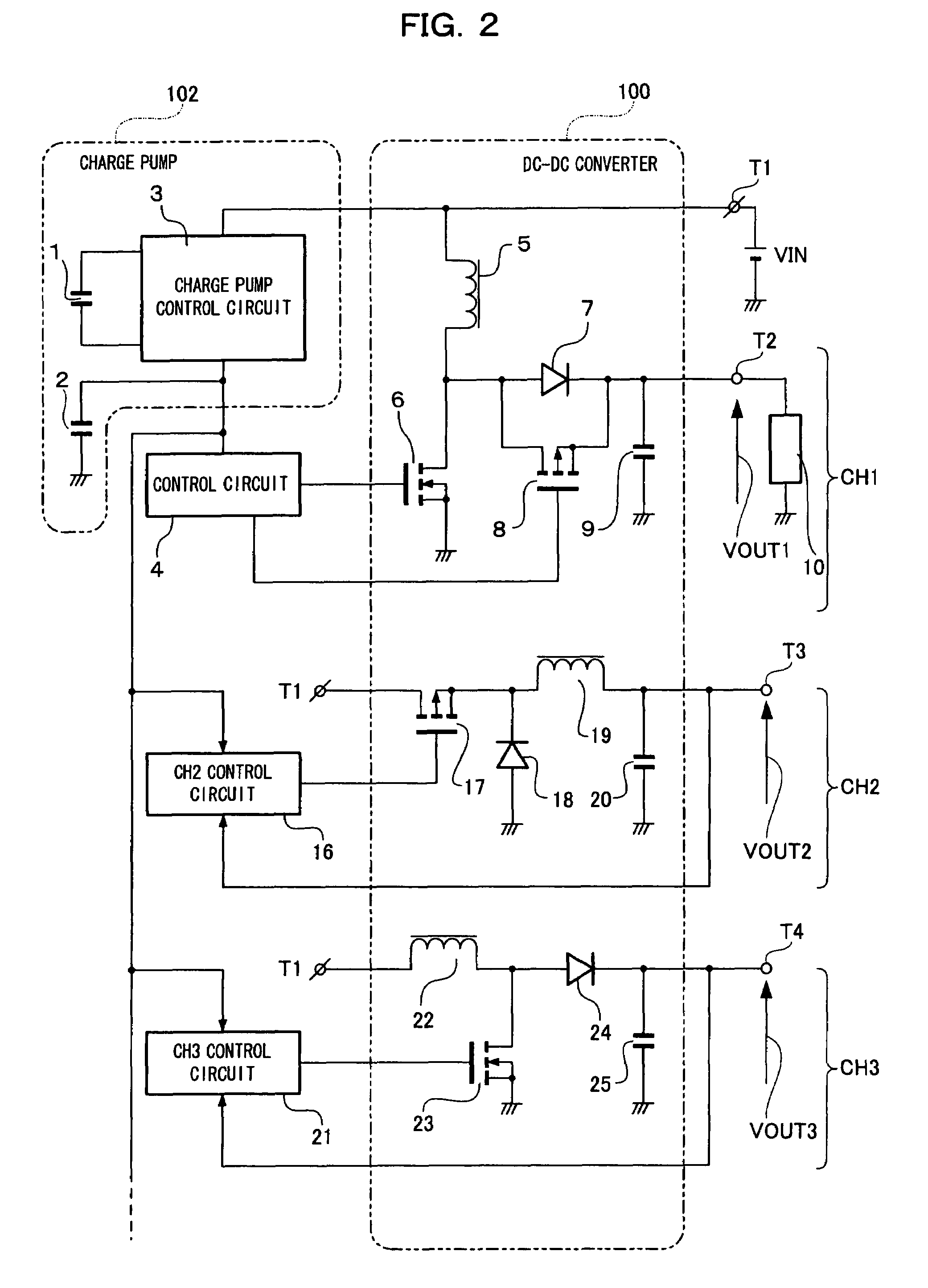
[0052]FIG. 2 shows switching power supply circuitry according to Embodiment 2 of the present invention.
[0053]The switching power supply circuitry is a switching power supply system for performing multi-channel control. A charge pump 102 and a control circuit 4 for an output voltage VOUT1 of a DC-DC converter 100 are similar to those of Embodiment 1. Further, the configurations of CH2, CH3, . . . are similar to those of FIG. 12 and thus the operations thereof are also similar to those of FIG. 12. For this reason, the detailed explanation thereof is omitted.
[0054]In the multi-channel control of the switching power supply circuitry shown in FIG. 2, the same operations as Embodiment 1 are performed from the supply of an input voltage VIN to the start of a charge pump control circuit 3.
[0055]As in Embodiment 1, a voltage boosted to a given potential by the charge pump control circuit 3 is monitored by the control circuit of each CH (for example, the control circuit 4, a CH2 control circu...
embodiment 3
[0058]FIGS. 4 to 6 show switching power supply circuitry according to Embodiment 3 of the present invention.
[0059]In the switching power supply circuitry of Embodiment 3 shown in FIG. 4, an input voltage VIN applied to an input terminal T1 is outputted as an output voltage VOUT to an output terminal T2 through a DC-DC converter 100.
[0060]In the DC-DC converter 100, a step-up converter is made up of a choke coil 5 having one end connected to the input terminal T1, a main switch 6 including an N-channel MOS transistor, a rectifier diode 7, a rectifier switch 8, and an output smoothing capacitor 9. To be specific, the anode of the rectifier diode 7, the drain of the main switch 6, and the drain of the rectifier switch 8 are connected to the other end of the choke coil 5 and the source of the main switch 6 is grounded. The output of the rectifier diode 7 and the rectifier switch 8 is smoothed by the output smoothing capacitor 9 and supplied to a load 10 connected to the output terminal ...
PUM
 Abstract
Description
Claims
Application Information
 - R&D
- Intellectual Property
- Life Sciences
- Materials
- Tech Scout
- Unparalleled Data Quality
- Higher Quality Content
- 60% Fewer Hallucinations
Browse by: Latest US Patents, China's latest patents, Technical Efficacy Thesaurus, Application Domain, Technology Topic, Popular Technical Reports.
© 2025 PatSnap. All rights reserved.Legal|Privacy policy|Modern Slavery Act Transparency Statement|Sitemap|About US| Contact US: help@patsnap.com


