Switching power supply circuitry

a power supply circuit and circuit technology, applied in the direction of pulse technique, process and machine control, instruments, etc., can solve the problems of overshoot on the output voltage vout, load b>10/b>, microcomputers, etc., to achieve positive start of the switching power supply circuitry, reduce power consumption, and stable operation of the control circui

Inactive Publication Date: 2007-09-13
COLLABO INNOVATIONS INC
View PDF3 Cites 111 Cited by
  • Summary
  • Abstract
  • Description
  • Claims
  • Application Information

AI Technical Summary

Benefits of technology

[0027]Moreover, the step-up power supply for a control circuit may include a stabilizing circuit such as a series regulator for stabilizing the output voltage of the step-up power supply for a control circuit and outputting the voltage. Thus it is possible to achieve a breakdown voltage and a stable operation of the control circuit.
[0028]The control circuit may include an error amplifier for generating an error signal of the DC output voltage and a target value and a PWM circuit for generating a driving pulse for controlling the switching operation of the step-up converter in response to the error signal. When the output voltage is not lower than a predetermined value, one of the error amplifier and the PWM circuit may be supplied with power from the DC output voltage instead of the output voltage of the step-up power supply for a control circuit. The control circuit may be, when the output voltage is not lower than the predetermined value, supplied with power from the DC output voltage instead of the output voltage of the step-up power supply for a control circuit. Further, the step-up power supply for a control circuit may stop operating when the output voltage is not lower than the predetermined value. This configuration can reduce power consumption during a normal operation.
[00

Problems solved by technology

Thus overshoot occurs on the output voltage VOUT and the load 10 (for example, a microcomputer) may deteriorate or break in the worst case.
Further, excessive rush current is generated on the input and degrades the performance of the battery used for the power supply.(2) Immediately after switching from “startup oscillation” to “main oscilla

Method used


Image

  • Switching power supply circuitry
  • Switching power supply circuitry
  • Switching power supply circuitry

Examples


embodiment 1

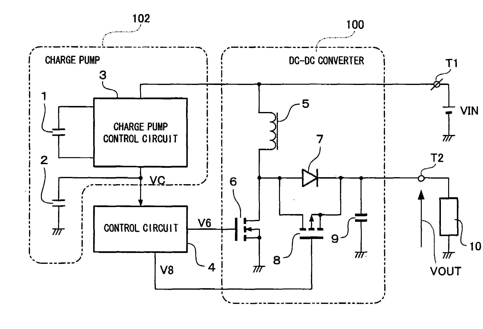
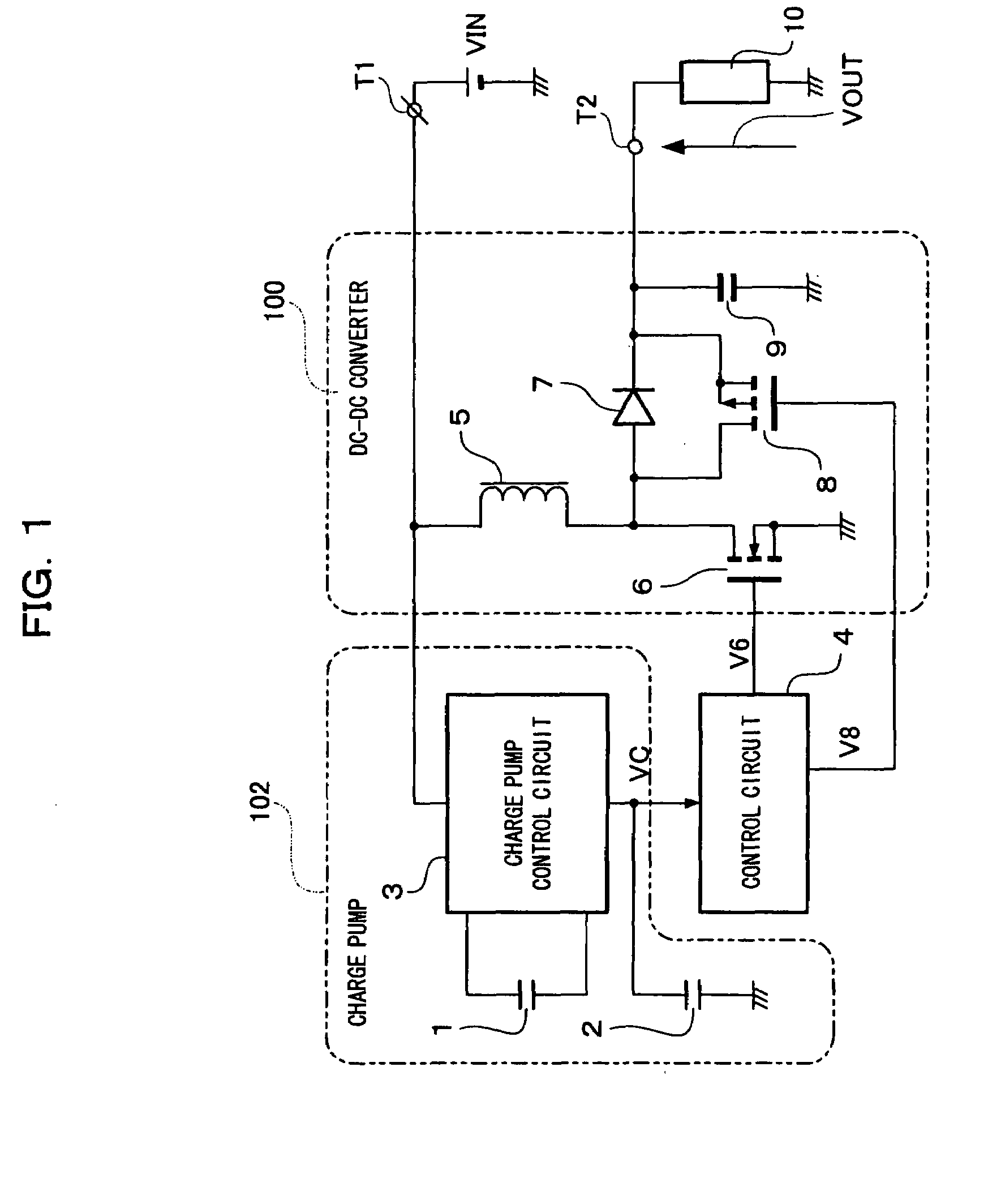
[0044]FIGS. 1 and 3 show switching power supply circuitry according to Embodiment 1 of the present invention.

[0045]In the switching power supply circuitry, an input voltage VIN applied to an input terminal T1 is outputted as an output voltage VOUT to an output terminal T2 through a DC-DC converter 100 acting as a step-up converter. In the DC-DC converter 100, a step-up converter is made up of a choke coil 5 having one end connected to the input terminal T1, a main switch 6 including an N-channel MOS transistor, a rectifier diode 7, a rectifier switch 8, and an output smoothing capacitor 9. To be specific, the anode of the rectifier diode 7, the drain of the main switch 6, and the drain of the rectifier switch 8 are connected to the other end of the choke coil 5 and the source of the main switch 6 is grounded. The output of the rectifier diode 7 and the rectifier switch 8 is smoothed by the output smoothing capacitor 9 and supply to a load 10 connected to the output terminal T2.

[0046...

embodiment 2

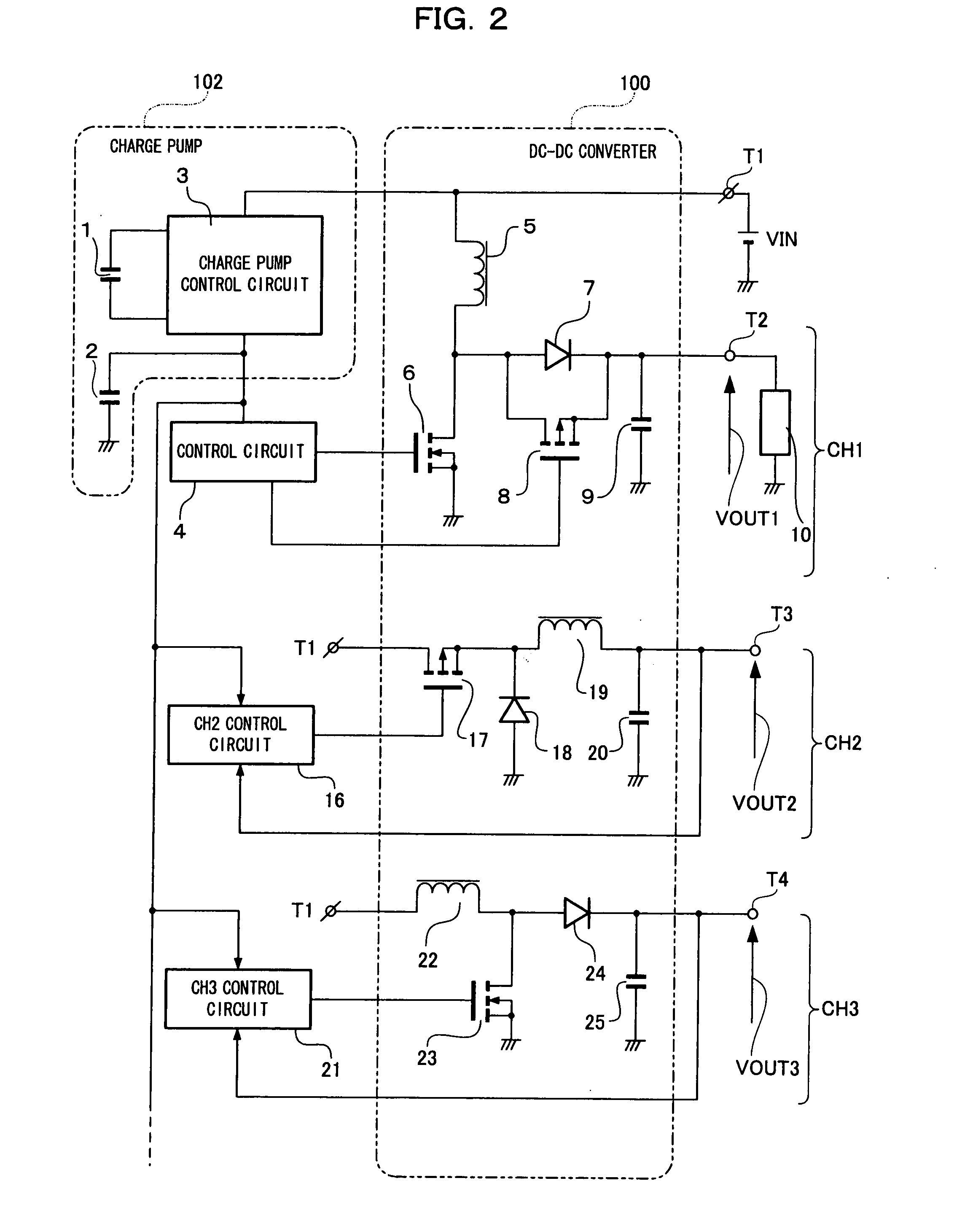
[0052]FIG. 2 shows switching power supply circuitry according to Embodiment 2 of the present invention.

[0053]The switching power supply circuitry is a switching power supply system for performing multi-channel control. A charge pump 102 and a control circuit 4 for an output voltage VOUT1 of a DC-DC converter 100 are similar to those of Embodiment 1. Further, the configurations of CH2, CH3, . . . are similar to those of FIG. 12 and thus the operations thereof are also similar to those of FIG. 12. For this reason, the detailed explanation thereof is omitted.

[0054]In the multi-channel control of the switching power supply circuitry shown in FIG. 2, the same operations as Embodiment 1 are performed from the supply of an input voltage VIN to the start of a charge pump control circuit 3.

[0055]As in Embodiment 1, a voltage boosted to a given potential by the charge pump control circuit 3 is monitored by the control circuit of each CH (for example, the control circuit 4, a CH2 control circu...

embodiment 3

[0058]FIGS. 4 to 6 show switching power supply circuitry according to Embodiment 3 of the present invention.

[0059]In the switching power supply circuitry of Embodiment 3 shown in FIG. 4, an input voltage VIN applied to an input terminal T1 is outputted as an output voltage VOUT to an output terminal T2 through a DC-DC converter 100.

[0060]In the DC-DC converter 100, a step-up converter is made up of a choke coil 5 having one end connected to the input terminal T1, a main switch 6 including an N-channel MOS transistor, a rectifier diode 7, a rectifier switch 8, and an output smoothing capacitor 9. To be specific, the anode of the rectifier diode 7, the drain of the main switch 6, and the drain of the rectifier switch 8 are connected to the other end of the choke coil 5 and the source of the main switch 6 is grounded. The output of the rectifier diode 7 and the rectifier switch 8 is smoothed by the output smoothing capacitor 9 and supplied to a load 10 connected to the output terminal ...


PUM


Abstract

An output voltage VC obtained by boosting an input voltage VIN by means of a charge pump control circuit 3 of a charge pump 102 is supplied as a power supply voltage to a control circuit 4 of a step-up converter. It is thus possible to eliminate the need for a conventional self-bias method, eliminate switching from startup oscillation to main oscillation of the conventional self-bias method upon startup, and overcome problems caused by the switching of oscillation states, thereby achieving switching power supply circuitry starting in a reliable and stable manner.

Description

FIELD OF THE INVENTION[0001]The present invention relates to switching power supply circuitry used as a power supply source of battery-driven equipment using, for example, a dry cell.BACKGROUND OF THE INVENTION[0002]Conventionally, switching power supply circuitry with a light weight, a small size, and high power efficiency is widely used for battery-driven equipment that uses a DC battery such as a dry cell as a power supply source and includes a portable terminal such as a mobile phone and a notebook computer.[0003]Particularly in recent years, as the number of battery-driven equipment such as electronic equipment increases, a low-voltage operation and a long-lasting operation of equipment, that is, long-life batteries are growing in demand for power supply circuitry, including this kind of switching power supply circuitry.[0004]FIG. 11 shows a conventional example described in Japanese Patent Laid-Open No. 2005-312191 and so on. In this switching power supply circuitry, an input ...

Claims


Application Information

Patent Timeline
IPC IPC(8): H02M3/18
CPCH02M1/36H02M3/073H02M2001/008H02M2001/0006H02M3/155H03K2217/0081H02M1/0006H02M1/008
Inventor KIMURA, KAZUHITOISHII, TAKUYA
Owner COLLABO INNOVATIONS INC
Why Eureka
Try Eureka