
Method of testing magnetic disc device

a magnetic disc and test method technology, applied in the field of testing a magnetic disc device, can solve the problems of track pitch deviation, inability to use too small track width, uneven track pitch in some cases, etc., and achieve the effect of accurate detection of track deviation and highly reliable tes

Inactive Publication Date: 2010-05-11
TOSHIBA STORAGE DEVICE CORP
View PDF11 Cites 0 Cited by
  • Summary
  • Abstract
  • Description
  • Claims
  • Application Information

AI Technical Summary

Benefits of technology

"The present invention provides a method for testing a magnetic disc device to detect a deviation of a track pitch and to measure the size of the deviation. The method involves writing data on every other track of a magnetic disc and then reading data from all tracks in which data is written. By measuring the error rate of reading data from a track, the position of the track can be calculated based on the first and second positions where an error rate reaches a predetermined level. This method allows for accurate detection of track deviations and provides a reliable test for the magnetic disc device."

Problems solved by technology

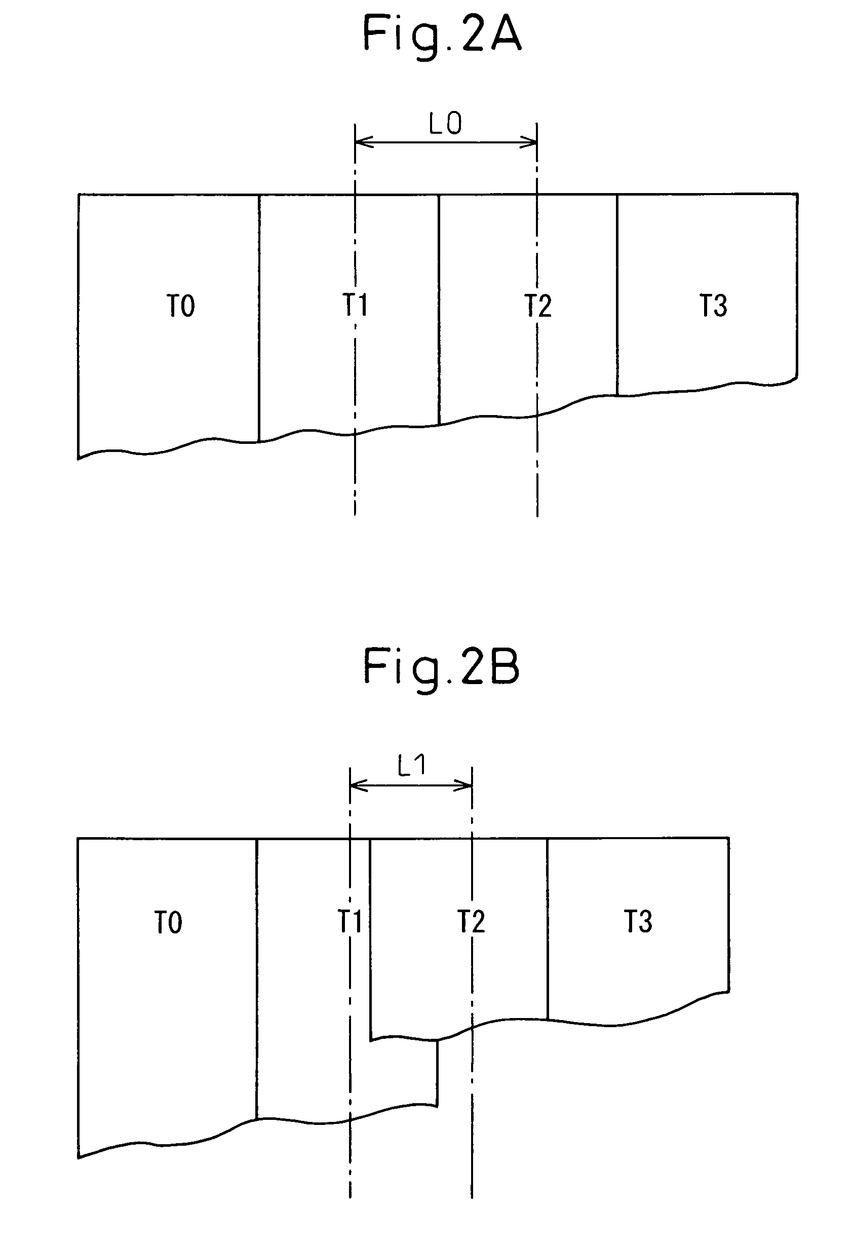
However, at the time of writing a servo pattern into a disc, a track can have an uneven track pitch in some cases.
This track-pitch deviation occurs when a voice coil motor that moves the write head to write the servo pattern does not rotate satisfactorily, or when a push pin that moves the head to be used by a servo track writer is contacted unsatisfactorily, or when an environmental shock occurs.
A track of which the track width has become too small cannot be used.
In other words, when there are narrow or wide tracks between the read head and the write head, it is not possible to accurately control the write head position on a predetermined track based on the read head position.
However, the technique described in this publication is not designed to detect a deviation of a track caused by an abnormal track pitch.

Method used


Image

  • Method of testing magnetic disc device
  • Method of testing magnetic disc device
  • Method of testing magnetic disc device

Examples


Embodiment Construction

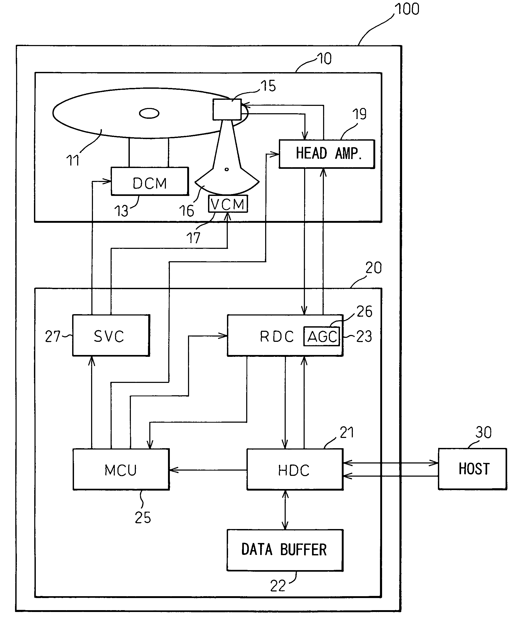
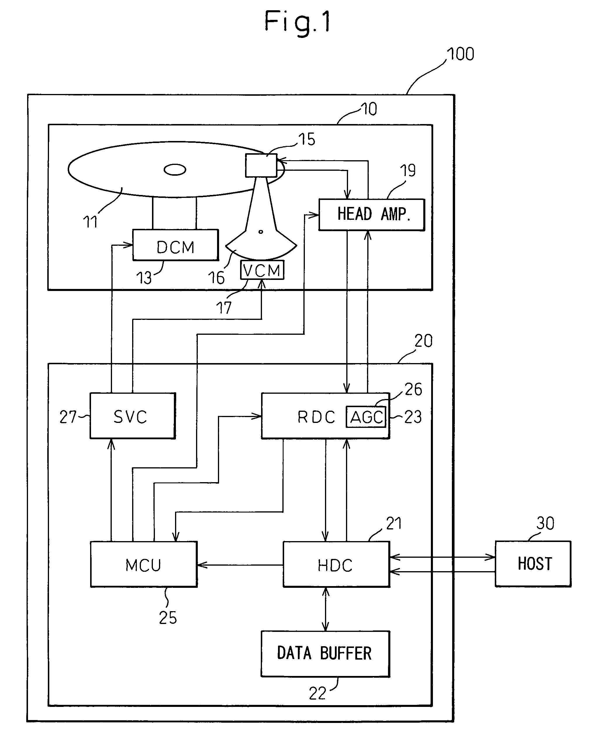
[0042]FIG. 1 shows a schematic configuration of one example of a magnetic disc device 100 using a magnetic disc according to the present invention. The magnetic disc device 100 has a disc enclosure 10 and a printed circuit board 20. The disc enclosure 10 includes a hard disc 11 as a magnetic recording medium, a direct current motor (DCM) 13 that rotates the hard disc 11, a head 15 that reads data from and writes data on the hard disc 11, an arm that supports the head 15, a voice coil motor 17 that turns the arm 16 to move the head 15 in the radial direction of the hard disc 11, and a head amplifier 19 that amplifies a read signal read by the head 15 and amplifies a write signal to be written by the head 15.

[0043]On the printed circuit board 20, there are disposed a servo controller 27 that controls a current supplied to the direct current motor (DCM) 13 and the voice coil motor 17, a read channel (RDC) 23 that receives a read signal from the head amplifier 19 and transmits a write s...


PUM

PropertyMeasurementUnit
distanceaaaaaaaaaa
timeaaaaaaaaaa
track widthaaaaaaaaaa

Abstract

A write head, which is positioned by reading a servo pattern with a read head, writes data on even tracks of a magnetic disc, and then writes data on odd tracks. Then a read head is positioned on a read position and sequentially reads all the written data. As a result, it is decided whether a read error has occurred. Further, positional deviation of the tracks, in which the read error occurs, is measured.

Description

BACKGROUND OF THE INVENTION[0001]1. Field of the Invention[0002]The present invention relates to a method of testing a magnetic disc device, and, more particularly, it relates to a method of testing a magnetic disc device to detect a deviation of a track attributable to an abnormal track pitch.[0003]2. Description of the Related Art[0004]In general, a magnetic disc device uses a write head to record data or information into a magnetic disc, and uses a read head to reproduce the recorded data or information. In recent years, most magnetic disc devices have a write head and a read head combined with each other, instead of using one head to read and write data. When the write head writes data on a disc, the read head is used to read positioning information or servo information, which is written in advance in a magnetic disc as a servo pattern, so as to position the write head on a predetermined track. When the read head reads, the read head is positioned on a predetermined track so as ...

Claims


Application Information

Patent Timeline
Patent Type & Authority Patents(United States)
IPC IPC(8): G11B5/09G11B27/36
CPCG11B5/59688G11B27/36G11B20/1816G11B2220/2516
Inventor ISHII, KOJI
Owner TOSHIBA STORAGE DEVICE CORP
Learn More