Method for machining using sacrificial supports

a technology of sacrificial supports and machining methods, which is applied in the direction of manufacturing tools, metal working apparatuses, welding/soldering/cutting articles, etc., can solve the problems of parts vibrating, reducing the accuracy of cutting, parts breaking or otherwise being damaged,

Active Publication Date: 2010-05-18
THE BOEING CO
View PDF4 Cites 74 Cited by
  • Summary
  • Abstract
  • Description
  • Claims
  • Application Information

AI Technical Summary

Problems solved by technology

The cutting tool may cause the part to vibrate during the cutting process.
This vibration can reduce the accuracy of the cut, leave vibration marks on the part due to variations in cut depth, and even cause the part to break or otherwise be damaged.
Consequently, machining processes for thin parts may be time consuming and costly, and may still cause unacceptable vibrations for very thin parts.

Method used


Image

  • Method for machining using sacrificial supports
  • Method for machining using sacrificial supports
  • Method for machining using sacrificial supports

Examples


Embodiment Construction

[0014]In the following detailed description, reference is made to the accompanying drawings that form a part hereof, and in which is shown by way of illustration specific illustrative embodiments in which the invention may be practiced. These embodiments are described in sufficient detail to enable those skilled in the art to practice the invention, and it is to be understood that other embodiments may be utilized and that various changes may be made without departing from the spirit and scope of the present invention. The following detailed description is, therefore, not to be taken in a limiting sense.

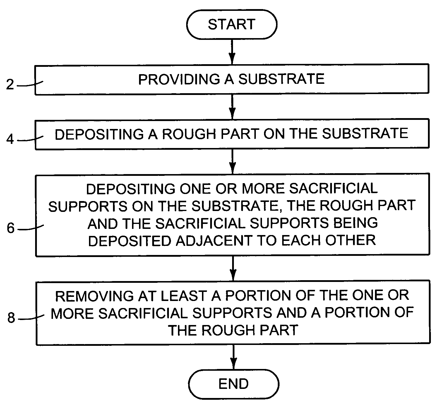
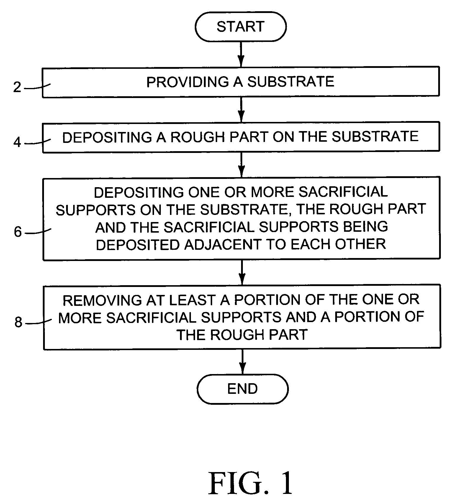
[0015]FIG. 1 illustrates a flow chart showing a process for machining parts, according to one embodiment of the present application. As illustrated in blocks 2 and 4 of FIG. 1, the process of the FIG. 1 embodiment comprises providing a substrate and then depositing a rough part on the substrate. One or more sacrificial supports are deposited on the substrate, as illustrated in block ...


PUM

PropertyMeasurementUnit
heightaaaaaaaaaa
depthaaaaaaaaaa
depthaaaaaaaaaa

Abstract

The present application is directed to a process for forming a machined part. The process comprises providing a substrate and depositing a rough part on the substrate. One or more sacrificial supports are deposited adjacent to the rough part on the substrate. All or a portion of the one or more sacrificial supports and a portion of the rough part are removed. Additional embodiments are directed to aircraft part assemblies, and aircraft parts made by the above process.

Description

BACKGROUND[0001]The present application relates to fabricating machined parts, and more particularly, to fabricating machined parts using sacrificial supports.[0002]Machined parts are employed, for example, in airplane manufacturing, automobile manufacturing, and a wide variety of other industries. When machining parts, a cutting tool is often used to remove material from a rough part or block of stock material. The cutting tool may cause the part to vibrate during the cutting process. This vibration can reduce the accuracy of the cut, leave vibration marks on the part due to variations in cut depth, and even cause the part to break or otherwise be damaged.[0003]Cutting tool vibration has been controlled using special cutting tool geometries and / or machining techniques designed to reduce vibration. For example, in certain machining techniques, small amounts of material may be removed at a slow rate using multiple cuts in order to avoid vibration. In one such technique, referred to h...

Claims


Application Information

Patent Timeline
Patent Type & Authority Patents(United States)
IPC IPC(8): B23P17/00
CPCB22F3/105B22F5/00B23K15/0086B23K26/34B26F3/004B23K26/3206B23K26/322B23K26/3226B23K2203/10Y10T29/4981B23K2203/14B23K26/32B23K2103/04B23K2103/10B23K2103/14B23K2103/50B33Y70/00B33Y80/00
Inventor STERN, ERIC J.HELVEY, AMY M.SWALLOW, CHRISTOPHER H.
Owner THE BOEING CO
Why Eureka
Try Eureka