Systems and methods for manufacturing reinforced weatherstrip

a technology of fabric reinforced foam and weather strip, which is applied in the field of methods, systems and apparatus for fabricating fabric reinforced foam substrate, can solve the problems of unreliable consideration or cost prohibitive prior art solutions, and achieve the effects of low friction, unprecedented performance characteristics, and quiet operation

Active Publication Date: 2010-05-18
AMESBURY GROUP
View PDF424 Cites 14 Cited by
  • Summary
  • Abstract
  • Description
  • Claims
  • Application Information

AI Technical Summary

Benefits of technology

[0010]Notwithstanding the benefits of substrates coated in accordance with the teachings of U.S. Pat. No. 5,192,586, there exists a need for more robust coated substrates to achieve heretofore unprecedented performance characteristics. FIGS. 11-19 and accompanying text describe embodiments of the present invention. The methods described in these figures may be incorporated into the methods of manufacture described in the former figures to produce fabric-reinforced coated substrates. The addition of a fabric layer or other reinforcing layer may be desirable for additional reinforcement, cushioning, or sealing. Certain fabrics have been elements of weatherstrip sealing products since their introduction in the 1980's, forming barriers against air and water infiltration as part of properly applied window and door system designs. The fabrics can contribute toward quiet operation, low friction (low operating forces), low water and air penetration, puncture resistance, tear resistance, colorability, UV resistance and long-term weatherability, chemical resistance, and thermal adhesion to olefin thermoplastic substrates.
[0012]In one aspect of this invention, the benefits of tear resistant, low friction polypropylene fabric are combined with the compression set resistance of TPV foam to provide a product of superior performance, utilizing an industry-proven TPV sealing component, while providing a cost effective production method of applying the fabric to the foam substrate. The fabric can be utilized to fully or partially encapsulate the foam core, and the extruded coating tie layer may bond to the inside of the fabric and to the stiffener for structural integrity and stability. In various embodiments, the fabric may be applied in strips to provide low friction areas, hinges, reinforced areas, chafe resistant areas, or color match areas in order to impart specific characteristics to the product. The underlying extruded layer of polymer may be simply a bonding material, requiring no UV protection or low friction characteristics, that being provided by the exterior layer, or it may be of lower cost material to simply act as a tie layer. The fabric may have a secondary extruded layer extruded onto or along the edges to protect them from catching and lifting with use. The secondary layer can utilize polyethylene, TPV, thermoplastic elastomer (TPE), polyester, polypropylene, acrylonitrite butadrene styrene (ABS), polystyrene ethylene butadiene styrene (SEBS), ethylene vinyl acetate (EVA), or other suitable and thermally compatible material.
[0019]Accordingly, it is an object of the present invention to provide a method and apparatus for coating a substrate which is simple and relatively low in cost. It is another object of the present invention to provide a method and apparatus for coating a substrate which produces a less oriented outer layer. It is still another object of the present invention to provide a method and apparatus for producing a substrate having a multiple-component outer layer. It is still another object of the present invention to provide a method and apparatus for providing a substrate with an outer layer of varying thickness which may be selectively applied to portions of the substrate. It is still another object of the present invention to overcome the disadvantages of the prior art.

Problems solved by technology

Other performance characteristics may also be enhanced by varying the polymer grade and the layers of polymer added to the skin layers over the foam in order to solve specific application issues; however, some prior art solutions become cost prohibitive or unreliable to consider due to their complexity or raw material cost.
One such challenge is the difficulty created by applying a weatherstrip in a meeting rail or in a jamb in a tilt double hung application, where lateral forces are generated on a highly flexible seal, causing it to tear.

Method used


Image

  • Systems and methods for manufacturing reinforced weatherstrip
  • Systems and methods for manufacturing reinforced weatherstrip
  • Systems and methods for manufacturing reinforced weatherstrip

Examples


Embodiment Construction

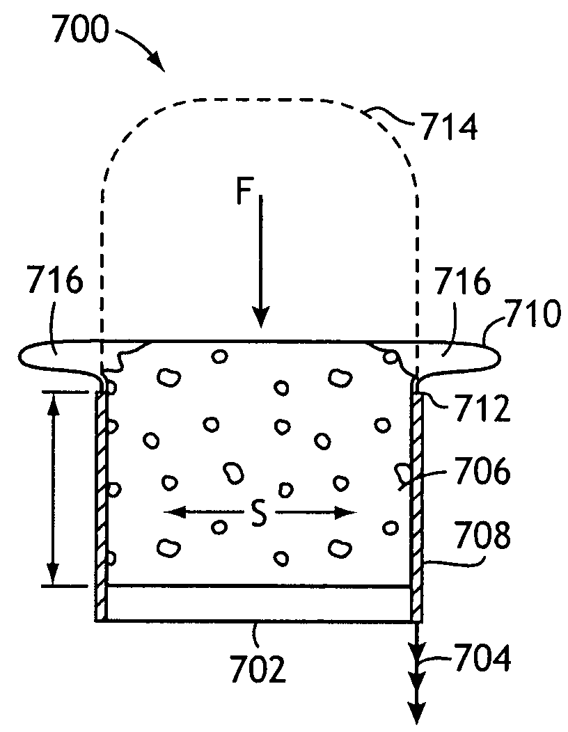
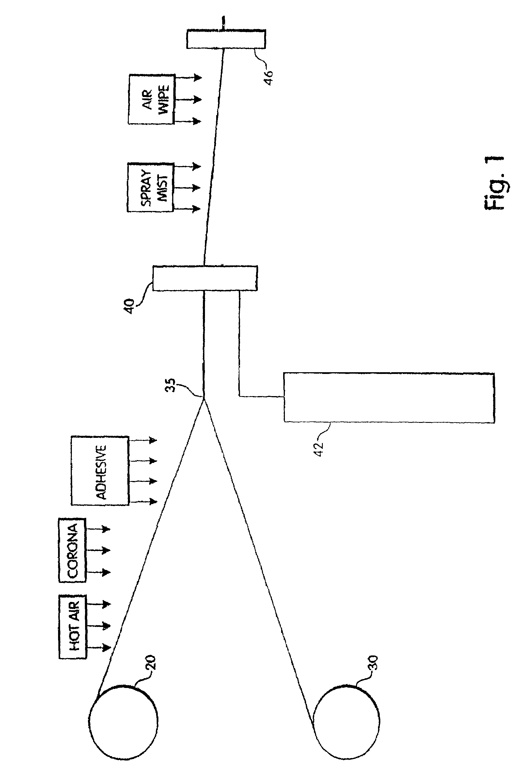
[0043]FIG. 1 schematically illustrates the overall operation of one embodiment of an apparatus for manufacturing coated weatherstrip. The product produced in this process is a weatherseal of the type shown in FIG. 4, which includes a foam body or profile with a thin skin or coating and having bonded thereto a stiffener which is used to attach the weatherseal to a structure, such as a door or window jamb. The stiffener is supplied from a reel 20. The stiffener is first heated to approximately 120°-240° F. by a hot air blower, for example, in order to slightly soften the stiffener and to facilitate the removal of twists or bends in the stiffener as it is uncoiled and subjected to longitudinal tension. The heating also increases the temperature of the stiffener which permits a more secure bond to be formed with the adhesive and skin material in processing steps described below.

[0044]The stiffener is then subjected to a corona treatment or other surface treatment method to enhance bondi...


PUM

PropertyMeasurementUnit
thicknessaaaaaaaaaa
depthaaaaaaaaaa
pressureaaaaaaaaaa

Abstract

Methods for manufacturing fabric-reinforced weatherstrip include incorporating a fabric application step into a process for making coated substrates. In one embodiment, a strip of the fabric from a roll of material may be applied directly onto a coating after it has been applied in a coat die to a foam profile, while the coating is still in the molten state. Alternatively, a fabric application plate may be attached to an upstream side of coating die with a fabric feed channel cut into the plate. The fabric follows the channel to contact and mate with the foam profile. The fabric applicator plate may be configured so as to exert pressure on only the part of the product where the fabric is being applied. Ultrasonic welding techniques may also be employed.

Description

CROSS-REFERENCE TO RELATED APPLICATION[0001]This application claims priority to and incorporates by reference herein in its entirety U.S. Provisional Patent Application Ser. No. 60 / 780,991, filed on Mar. 10, 2006.TECHNICAL FIELD[0002]The present invention generally relates to methods, systems, and apparatus for fabricating a fabric-reinforced (clad) coated foam substrate, and the products manufactured by the disclosed methods, systems, and apparatus.BACKGROUND OF THE INVENTION[0003]Non-reinforced coated substrates may be manufactured by a number of methods, as described with reference to FIGS. 1-10 and in the accompanying text. The methods and systems associated with the manufacture of non-reinforced coated substrates are also described in U.S. Pat. No. 5,192,586 to Mertinooke et al., the disclosure of which and all references of record therein and in the reexamination proceeding thereof are incorporated by reference herein in their entireties.[0004]In many applications, it is desir...

Claims


Application Information

Patent Timeline
Patent Type & Authority Patents(United States)
IPC IPC(8): B29C65/00B32B27/00B65C9/25B29C48/09B29C48/12B29C48/30B29C48/355
CPCB29C44/326B29C66/727B29C47/025B29C47/026B29C47/128B29C65/086B29C65/562B29C66/81463B29C66/83411B29C66/83413E06B7/2305B29C66/8432B29C63/044B29C65/02B29C65/56B29C65/62B29K2023/06B29K2023/083B29K2023/12B29K2055/02B29K2105/04B29L2031/003B29L2031/006B29L2031/26B29C47/0023B29C47/021B29C47/04B29C47/065B29C66/7292B29C66/72941B29C47/003B29C66/433B29C66/73771B29C66/73921B29C66/524B29C66/5326B29C66/71B29C66/0242Y10T428/249953B29C48/154B29C48/304B29C48/12B29C48/21B29C48/355B29K2101/12B29K2033/08B29K2075/00B29K2077/00B29K2083/00B29C48/34B29C48/156B29C48/0013B29C48/09B29K2067/00B29K2023/08B29K2023/0625B29K2021/003B29K2021/00B29K2019/00B29K2007/00B29C31/04B29C31/08B29C35/02B29C48/15B29C48/155B29C48/16B29C48/151B32B5/18B32B5/245B29C65/08E06B7/2314
Inventor HUNTRESS, JOHN E.MERTINOOKE, PETER
Owner AMESBURY GROUP
Why Eureka
Try Eureka