Wiring distribution device for an electronics rack

a technology for wiring distribution and electronics racks, applied in the direction of electrical apparatus casings/cabinets/drawers, inorganic insulators, hermetically sealed casings, etc., can solve the problems of poor coordination of current wiring systems or design for ease of installation and consistency

Active Publication Date: 2010-05-18
LEGRAND AV INC
View PDF11 Cites 63 Cited by
  • Summary
  • Abstract
  • Description
  • Claims
  • Application Information

AI Technical Summary

Problems solved by technology

Current wiring systems are not well coordinated or designed for ease of instal

Method used


Image

  • Wiring distribution device for an electronics rack
  • Wiring distribution device for an electronics rack
  • Wiring distribution device for an electronics rack

Examples


Embodiment Construction

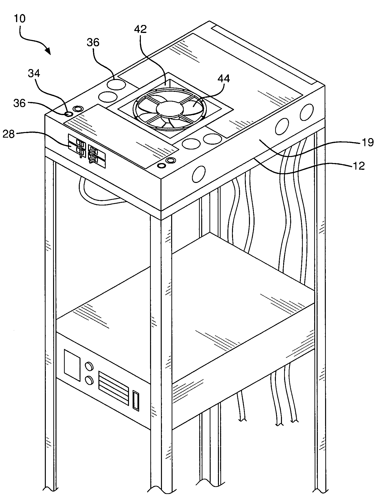
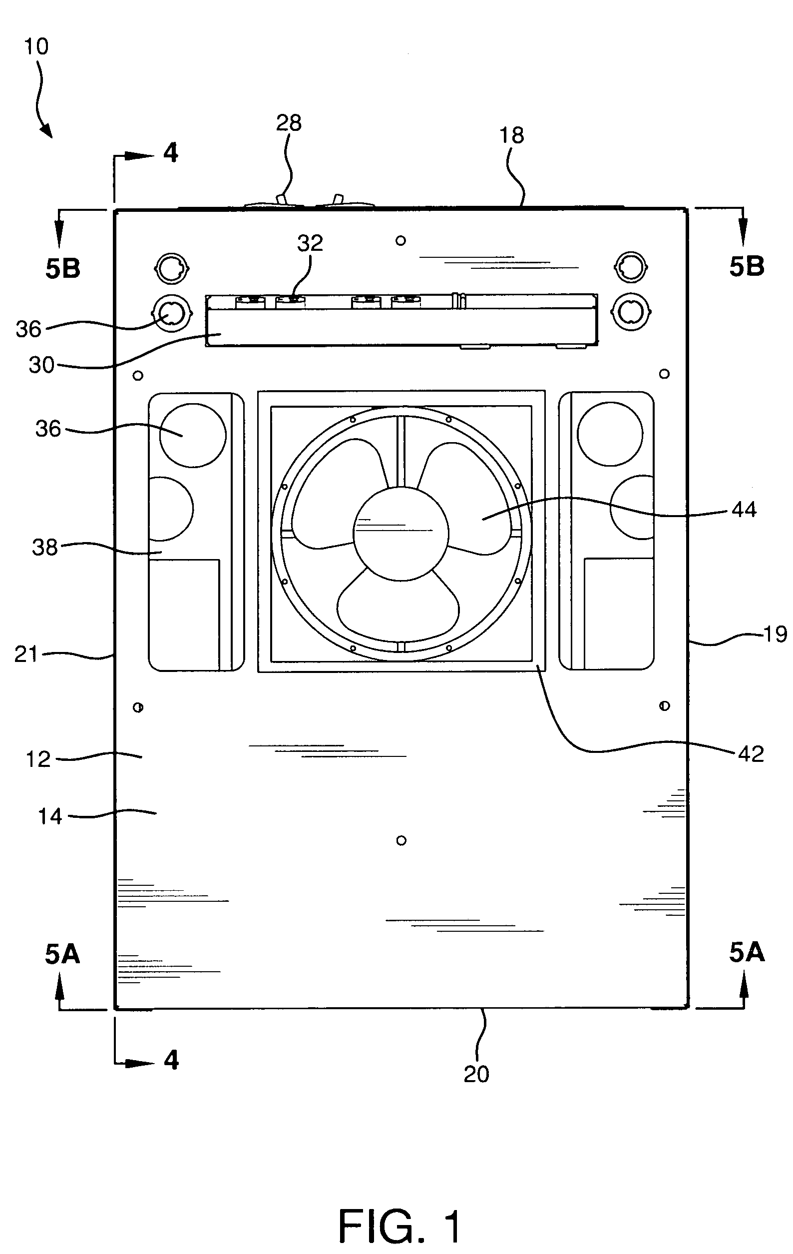
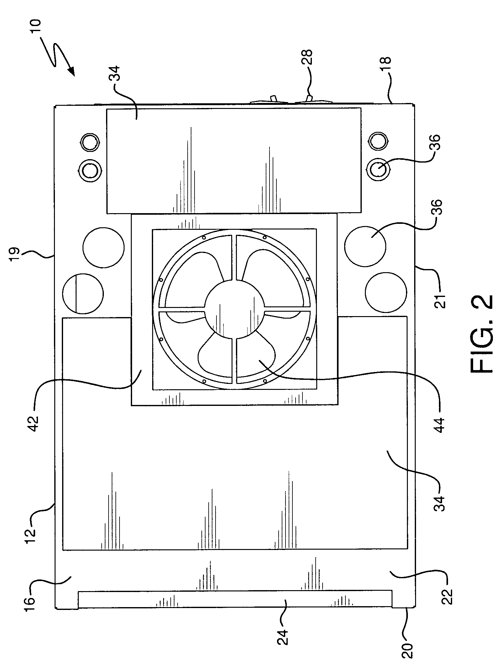
[0017]Referring now to the drawings which illustrate several preferred embodiments of the invention, a wiring distribution device is shown for use on an electronics rack. As will be discussed in more detail below, the distribution device preferably includes a high voltage (class 1 wiring) side, a low-voltage (class 2 wiring) side, a cooling device, a power distribution device, and power conditioning device.

[0018]FIGS. 1 and 2 are bottom and top views, respectively, of the wiring distribution device 10, which preferably mounts to the top of a rack or cabinet containing electronic devices (not shown). The distribution device includes a housing 12, which has a bottom 14, a top 16, front and rear faces or walls 18 and 20, respectively, and side walls, 19, 21. The housing 12 preferably includes upper and lower sections, which together define an enclosure with an interior that includes at least two internal chambers or compartments 26. The lower section 24 in the illustrated embodiment of...


PUM


Abstract

A wiring and power distribution device for a cabinet housing electronic equipment. The distribution device includes a plurality of compartments. Each compartment adapted to contain an electronic component, such as an uninterruptible power supply, a power-conditioning device, or a power distribution center containing circuit breakers. The distribution device also includes a cooling compartment, including a fan or passive convective chimney arranged to cool the interior of the cabinet with ambient air. The distribution device provides a single input point for power and signal wiring, and at least one output point for connection to the electronic devices contained within the cabinet.

Description

FIELD OF THE INVENTION[0001]The present invention relates generally to electronics racks, and particularly, to systems for providing power, temperature, and wiring management to components mounted in such racks.BACKGROUND OF THE INVENTION[0002]It is known to provide a rack or cabinet in which electronic components may be mounted. Existing racks may provide surge suppressors or power strips integrated into the rack; components may be plugged into these strips to make movement of the rack or cabinet more convenient. However, components mounted in such cabinets must still be wired individually to one another and to a power source which is typically located external to the rack or enters the rack from multiple locations.[0003]Also, installation personnel must connect wiring to the rack or cabinet, as well as the components, in the field, after the electronic components are integrated into the cabinet. The field installation personnel must then work inside the cabinet to interconnect the...

Claims


Application Information

Patent Timeline
IPC IPC(8): H05K7/20
CPCH05K7/1457H05K7/20736H05K7/20581
Inventor SCHLUTER, ROBERT
Owner LEGRAND AV INC
Why Eureka
Try Eureka