
Modular power distribution center

a technology of module power distribution and distribution center, which is applied in the direction of electrical apparatus, clip conductor connection, printed circuit, etc., can solve the problems of affecting product quality, affecting product quality, and increasing the complexity of vehicle electrical systems

Active Publication Date: 2009-09-22
AEES INC
View PDF108 Cites 8 Cited by
  • Summary
  • Abstract
  • Description
  • Claims
  • Application Information

AI Technical Summary

Benefits of technology

"The present invention is a modular power distribution center that allows for the integration of electronics modules onto printed circuit boards. It uses connectors for interconnectivity, instead of hard wiring, and can be easily integrated into vehicles. The center includes a modular housing with at least one receptacle for engaging a device and at least one socket for I / O connections. The housing has at least one printed circuit board with a primary buss and at least one device interface buss connected to it. The printed circuit board has a primary conductive strip, a terminal connected to it, and at least one device interface buss connected to it, which corresponds to the receptacle of the housing. The center allows for easy adjustability and can be customized for different vehicle configurations. The method for distributing electrical power in a vehicle involves connecting a power buss to a printed circuit board with device interface buss and I / O connections, enclosing the printed circuit board in a modular housing, and providing a modular upper plate and lower plate for electrical device connections. The technical effects of the invention include improved flexibility, customization, and ease of integration into vehicles."

Problems solved by technology

The complexity of vehicle electrical systems has grown almost exponentially since the automobile's introduction.
Hand wiring is very costly, and manual wiring operations are a source of wiring errors that negatively impact product quality.
Although this approach typically yields a higher quality product, tooling costs can be high for both the plastic shells and the stampings since virtually every automobile model requires a unique distribution system.
The principal disadvantage of the flex circuit approach is that the conductive layers are very thin, and the high current densities required in vehicle power distribution can lead to overheating and possible eventual failure.
In summary, existing modular power distribution centers are hard wired and do not allow for modular integration of electronics.

Method used


Image

  • Modular power distribution center
  • Modular power distribution center
  • Modular power distribution center

Examples


Embodiment Construction

[0047]The present invention includes a modular power distribution center that provides electrical connections of the device interface buss through mechanical connectors and also provides for integration of the electronic modules onto printed circuit board architectures.

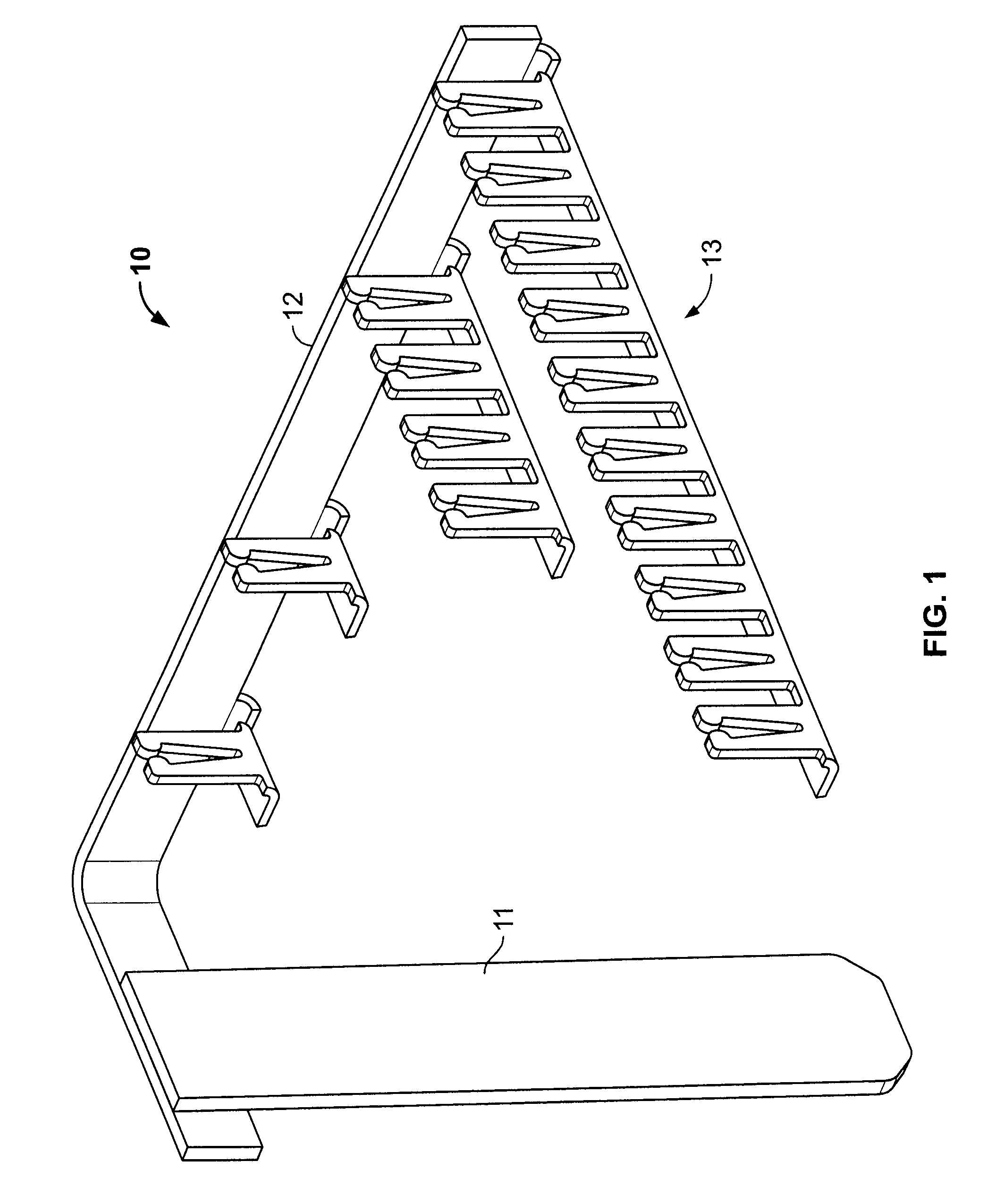
[0048]FIG. 1 depicts one embodiment of modular power buss 10 (also referred to as primary bus) which may include a positive battery terminal 11 (also referred to as B+ terminal), a primary strip 12, and at least one device interface buss 13. The primary buss 10 may be formed of conductive material such as copper. In one embodiment, the components of the primary buss 10 are formed from a sheet material by a stamping operation.

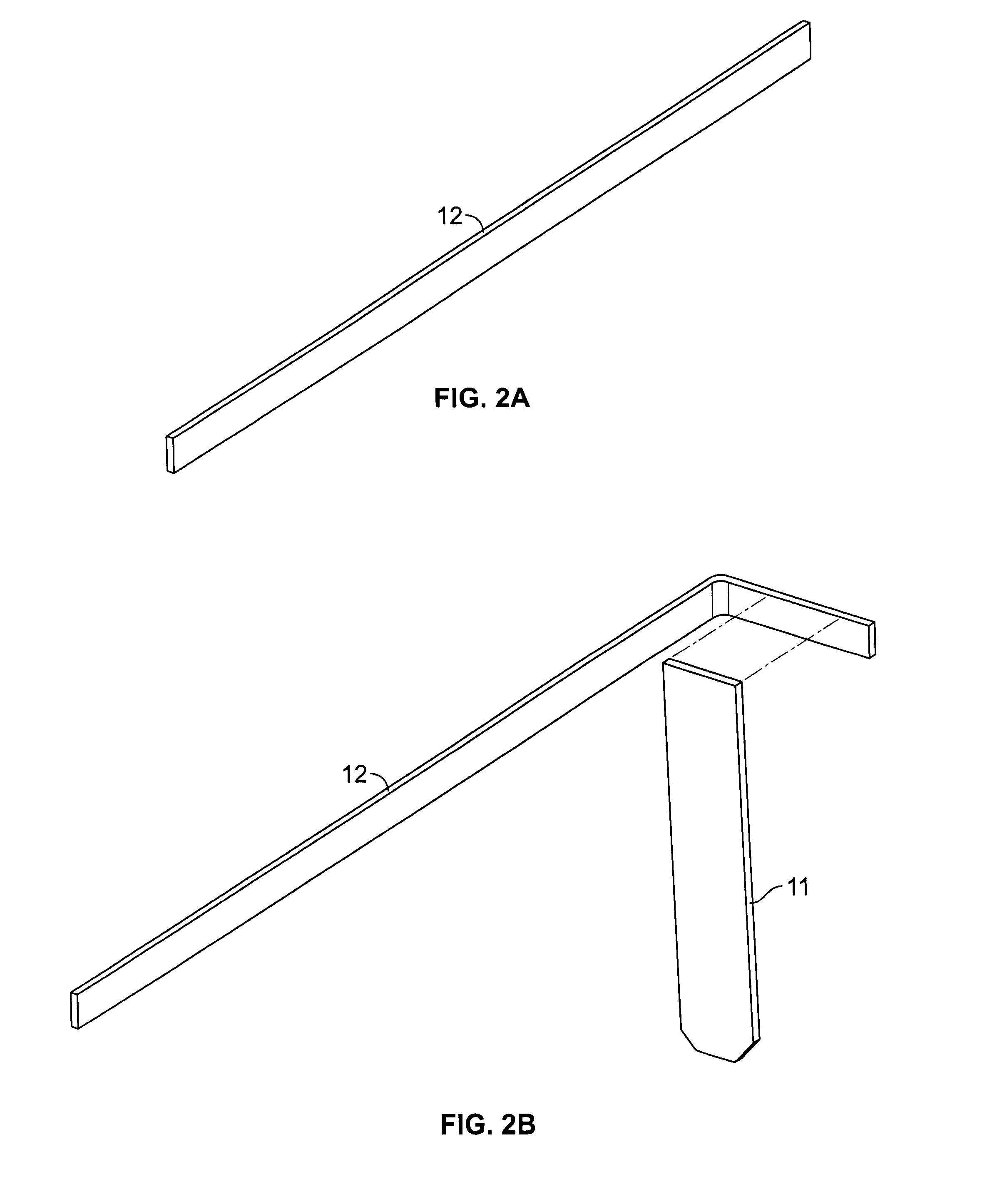
[0049]Referring to FIG. 2A, primary strip 12 may be cut to a preselected length along a first direction to provide for attachment of the device interface buss 13. The length and orientation of the primary bus strip 12 may be selected to contribute to the final electrical device layout to the modul...


PUM


Abstract

There is disclosed a modular power distribution center that utilizes connectors for interconnectivity, as opposed to hard wiring and allows for the integration of electronics modules onto printed circuit board architecture.

Description

[0001]This application claims the benefit of Provisional Application Ser. No. 60 / 825,020, filed Sep. 8, 2006.FIELD OF THE INVENTION[0002]This invention relates generally to an electrical power distribution center and more particularly to method and apparatus for distributing electrical power in a vehicle.BACKGROUND OF THE INVENTION[0003]The first motorized vehicles had little in the way of an electrical system. All that was required was some way to generate and distribute an ignition potential to each of the cylinders of the small, internal combustion engine that powered these early vehicles. The need to see the road ahead during nighttime operation gave rise to the first electrical accessory: headlights. Interior illumination was added for the operator's convenience, and a single tail light was considered adequate. Turn signal lights followed, but the simple vehicle radio receiver did not make its appearance until a number of years later. The modern automobile is an impressive coll...

Claims


Application Information

Patent Timeline
Patent Type & Authority Patents(United States)
IPC IPC(8): H01R12/00
CPCH01R4/06H01R9/226H01R43/027H01R9/2425
Inventor BOILEAU, DANIEL E.BAGCHI, ANKOORLIKE, NATHANYOUNG, ROBERT J.
Owner AEES INC
Learn More