Radio device and interference avoiding method by transmission power control
- Summary
- Abstract
- Description
- Claims
- Application Information
AI Technical Summary
Benefits of technology
Problems solved by technology
Method used
Image
Examples
first embodiment
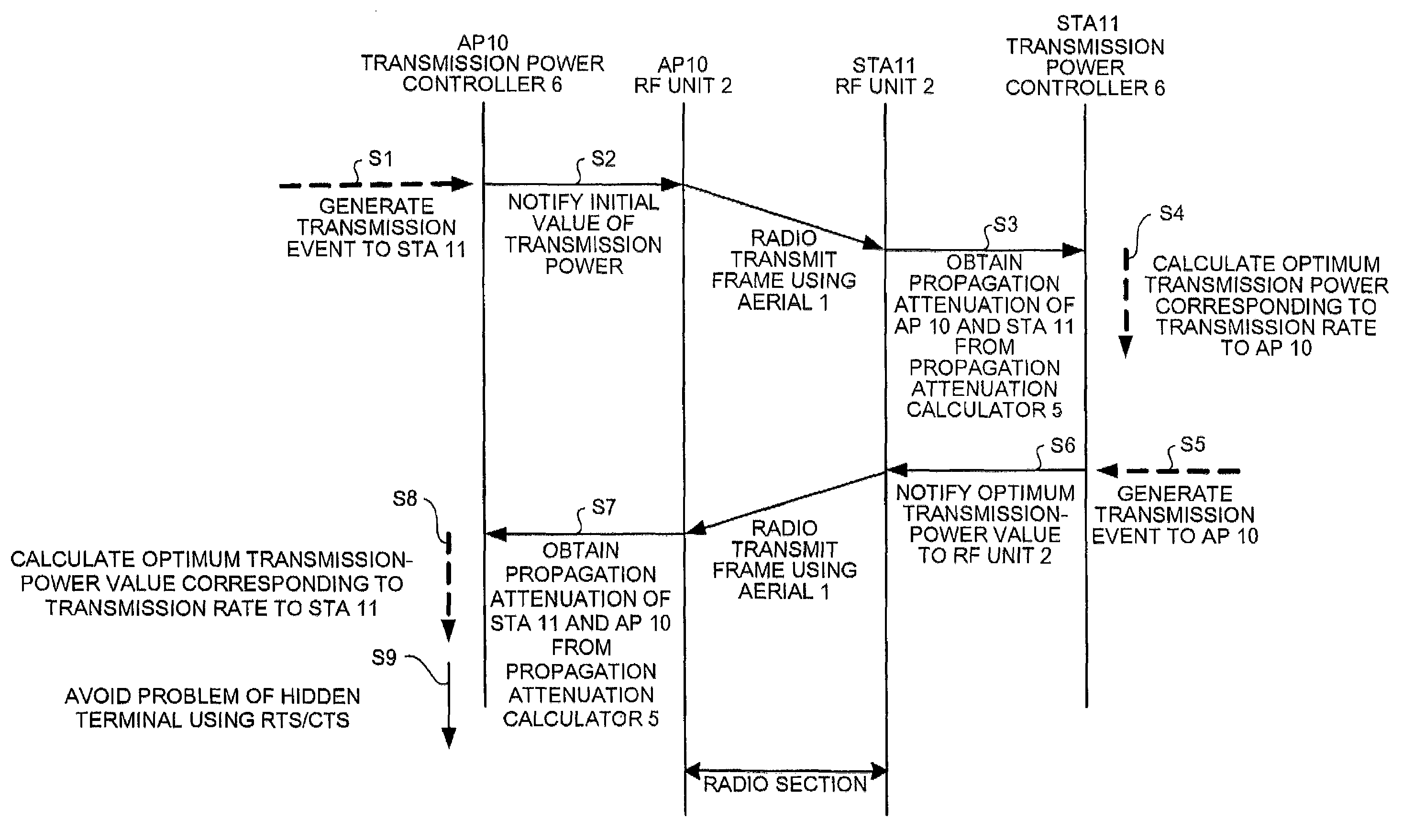
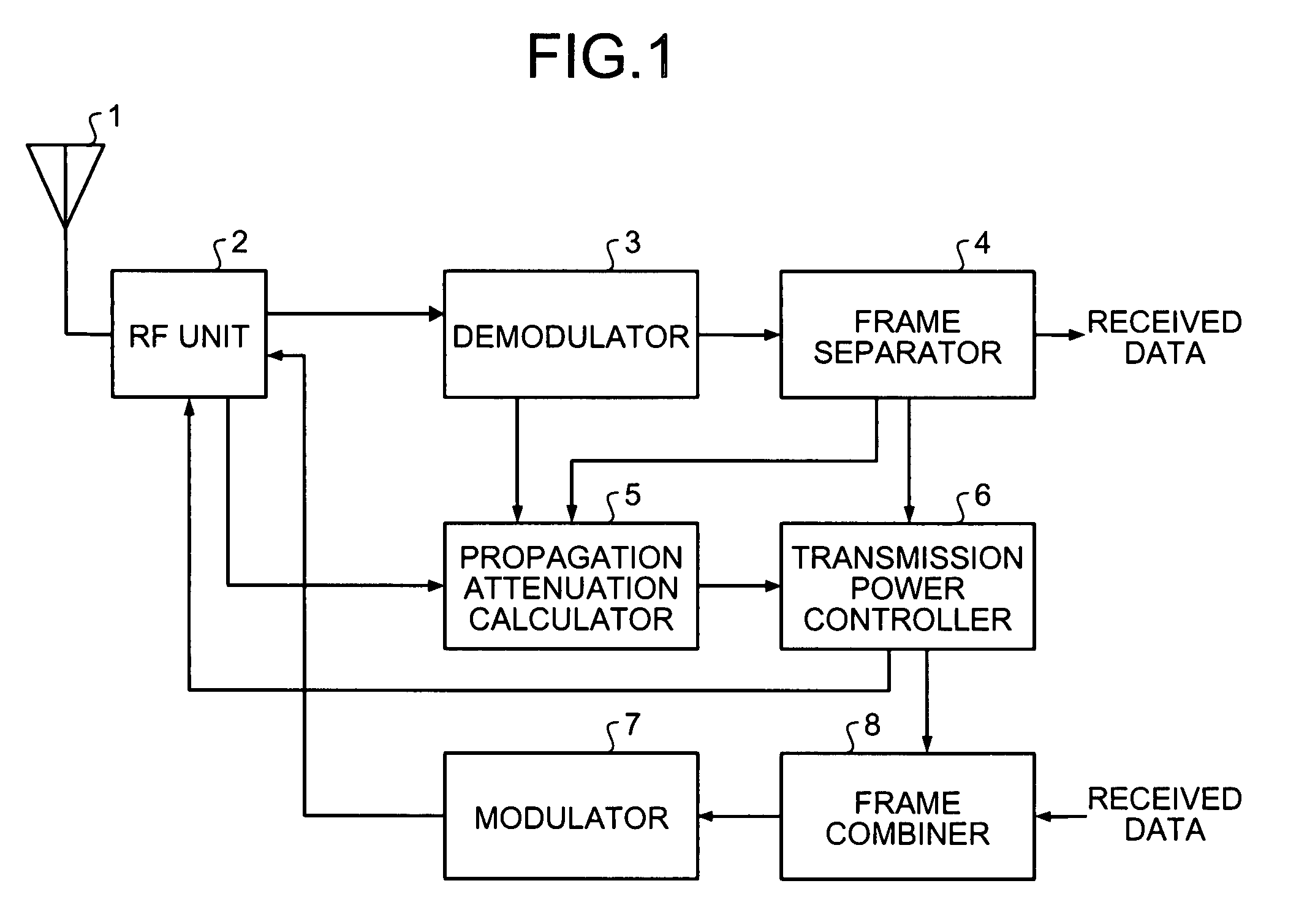
[0054]A first embodiment of the present invention is explained with reference to FIG. 1 to FIG. 5. FIG. 1 depicts a configuration of a radio device according to the first embodiment of the present invention. The radio device includes an aerial 1, an RF unit 2, a demodulator 3, a frame separator 4, a propagation attenuation calculator 5, a transmission power controller 6, a modulator 7, and a frame combiner 8.
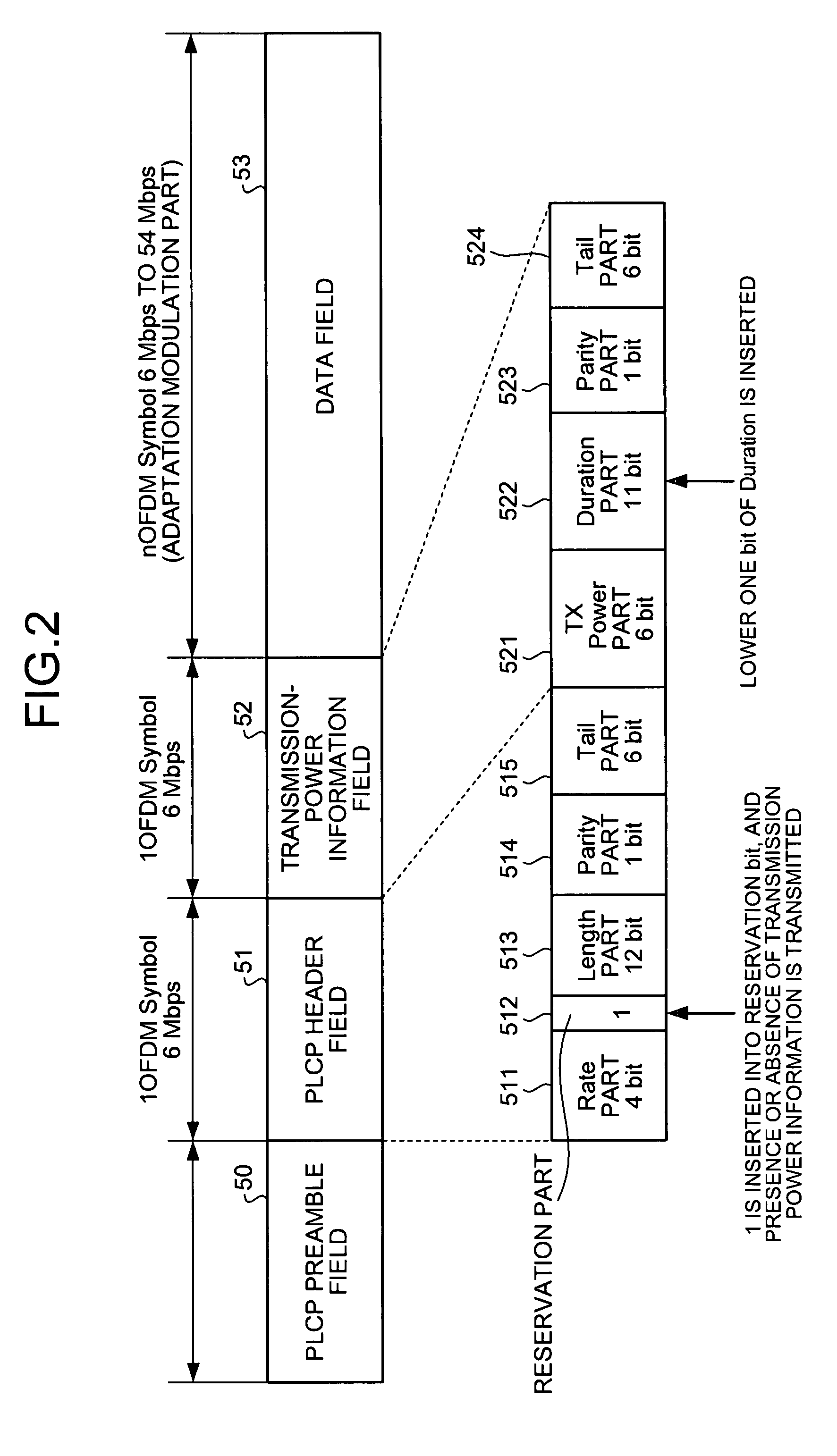
[0055]The aerial 1 converts an electromagnetic wave signal into an electric signal, and outputs the electric signal to the RF unit 2, and also converts an electric signal received from the RF unit 2 into an electromagnetic wave signal for transmission. The RF unit 2 amplifies an electric signal input from the aerial 1, frequency-converts the amplified electric signal into a baseband signal, outputs the baseband signal to the demodulator 3, and outputs information necessary to calculate a reception-power value to the propagation attenuation calculator 5 as first reception-power i...
second embodiment
[0100]A second embodiment of the present invention is explained below with reference to FIG. 6 and FIG. 7. FIG. 6 depicts a configuration of a radio LAN system according to the second embodiment. In FIG. 6, radio devices 20 to 23 have internal configurations shown in FIG. 1. Among the radio devices 20 to 23, the radio devices 20 and 22 are APs, and the radio devices 21 and 23 are STAs. A first basic service set (hereinafter, BSS (1)) 24 includes the AP 20 and the STA 21. A second basic service set (hereinafter, BSS (2)) 25 includes the AP 22 and the STA 23. In carrying out communications within the same BSS (between the AP 20 and the STA 21, and between the AP 22 and STA 23), transmission power is optimized following a procedure same as that of the first embodiment, and therefore explanations thereof will be omitted.
[0101]When communication is carried out between the STA 21 and the AP 22 of different BSSs, the STA 21 and the AP 22 are within a distance in which an electromagnetic wa...
third embodiment
[0113]A third embodiment of the present invention is explained below with reference to FIG. 8 to FIG. 10. FIG. 8 depicts a configuration of a radio LAN system according to the third embodiment. In FIG. 8, radio devices 30 to 34 have the internal configurations shown in FIG. 1. Among the radio devices 30 to 34, the radio devices 30 and 33 are APs, and the radio devices 31, 32, and 34 are STAs. A BSS (1) 35 includes the AP 30, the STA 31, and the STA 32. A BSS (2) 36 includes the AP 33 and the STA 34. Like in the second embodiment, interference occurs between different BSSs, between the STA 31 and the AP 33. In the third embodiment, a procedure of the STA 31 avoiding the interference to the AP 33 is the same as that explained in the second embodiment, and therefore explanations thereof will be omitted.
[0114]The communication procedure after the interference control by the STA 31 is explained with reference to FIG. 9. First, to communicate with the AP 30, the STA 31 broadcasts a contro...
PUM
 Abstract
Description
Claims
Application Information
 - R&D
- Intellectual Property
- Life Sciences
- Materials
- Tech Scout
- Unparalleled Data Quality
- Higher Quality Content
- 60% Fewer Hallucinations
Browse by: Latest US Patents, China's latest patents, Technical Efficacy Thesaurus, Application Domain, Technology Topic, Popular Technical Reports.
© 2025 PatSnap. All rights reserved.Legal|Privacy policy|Modern Slavery Act Transparency Statement|Sitemap|About US| Contact US: help@patsnap.com


