Intensively cooled trailing edge of thin airfoils for turbine engines

a technology of turbine blades and airfoils, which is applied in the field of intensive cooling of trailing edges of hollow turbine blades, can solve the problems of easy failure, difficult cooling of trailing edges of turbine blades, and easy creep or oxidation of trailing edges during operation, so as to improve convective cooling of trailing edges and increase flow

Inactive Publication Date: 2010-05-25
SIEMENS ENERGY INC
View PDF20 Cites 13 Cited by
  • Summary
  • Abstract
  • Description
  • Claims
  • Application Information

AI Technical Summary

Benefits of technology

[0014]Yet another advantage of the invention is that the trailing edge cooling cavity may be designed so that the impingement effect is not distorted by the cross-flow of cooling fluid.
[0015]Another advantage of the invention is that the cooling system provides improved convective cooling of the trailing edge by increasing the flow of cooling fluid in the trailing edge cooling cavity proximate to the trailing edge of the blade.
[0016]These and other embodiments are described in more detail below.

Problems solved by technology

In addition, turbine blades often contain cooling systems for prolonging the life of the blades and reducing the likelihood of failure as a result of excessive temperatures.
The trailing edge of a turbine blade is difficult to cool because the trailing edge is often too thin to effectively cool using known embodiments.
Because the trailing edge of a blade is difficult to cool and is often exposed to both high temperatures and high loads, the trailing edge may suffer from creep or oxidation during operation.
The detrimental effects may be most pronounced in the radially outward portion of the blade proximate to the blade tip because the elongated airfoil is thinner at the tip.
The problem is generally most severe in the rear stages of a turbine where the entire elongated airfoil is generally thinner than the elongated airfoils of the front stages.

Method used


Image

  • Intensively cooled trailing edge of thin airfoils for turbine engines
  • Intensively cooled trailing edge of thin airfoils for turbine engines
  • Intensively cooled trailing edge of thin airfoils for turbine engines

Examples


Embodiment Construction

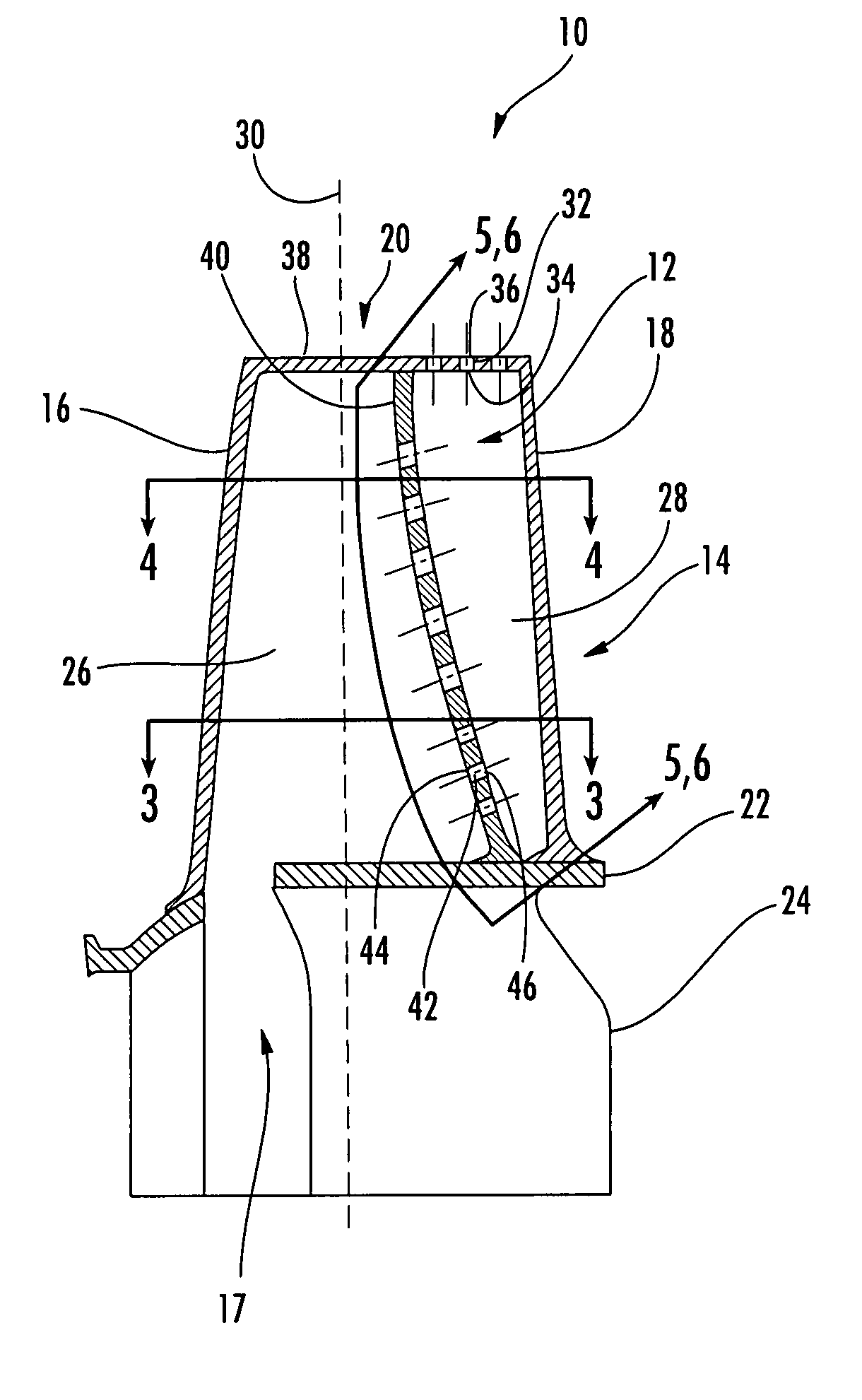
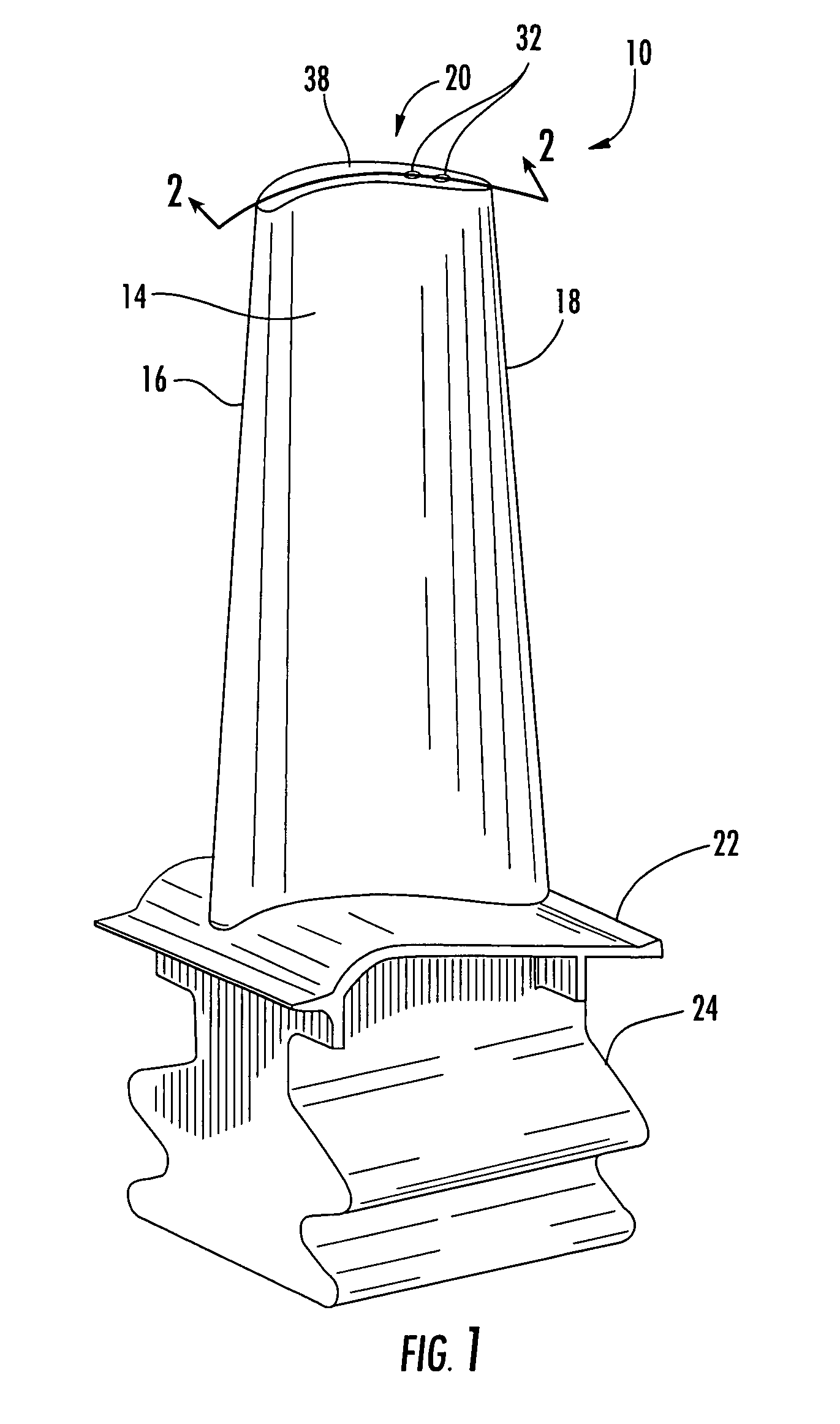
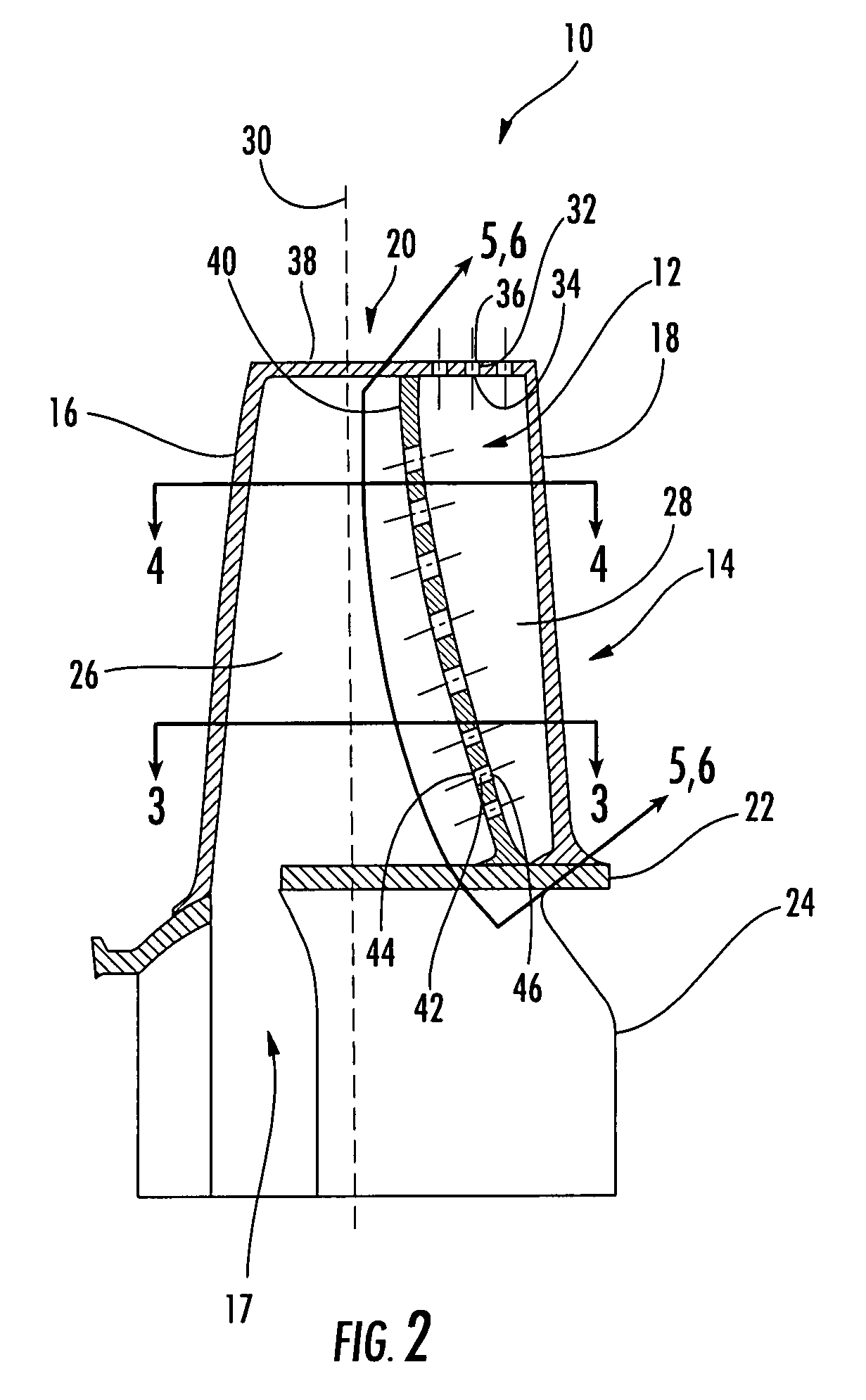
[0026]As shown in FIGS. 1-8, this invention is directed to a cooling system 12 usable in a turbine blade 10 that is configured to be used in rear stages of a turbine of a turbine engine. The cooling system 12 may be configured to cool aspects of the trailing edge 18 despite the relatively thin thickness of the turbine blade 10 proximate to the trailing edge 18. In particular, the cooling system 12 may exhaust cooling fluids through the tip 20 rather than through the trailing edge 18, thereby not further weakening the region of the airfoil 10 proximate to the trailing edge 18.

[0027]In one embodiment, the turbine blade 10 may include a generally elongated blade 14 having a leading edge 16, a trailing edge 18, a tip 20, and a platform 22 that is positioned generally orthogonal to the generally elongated blade 14 and located at an end of the generally elongated blade 14 opposite the tip 20. The trailing edge 18 may be a nonperforated trailing edge 18 that lacks any exhaust orifices, as ...


PUM


Abstract

A cooling system designed to cool the trailing edge of a turbine blade usable in rear stages of a turbine engine. The turbine blade may have a leading edge cooling cavity and a trailing edge cooling cavity separated by an impingement rib. The cooling system may exhaust cooling fluids through the tip of the turbine blade rather than through the trailing edge of the turbine blade to prevent premature failure at the trailing edge of the turbine blade.

Description

FIELD OF THE INVENTION[0001]This invention is directed generally to turbine blades, and more particularly to cooling systems in hollow turbine blades.BACKGROUND[0002]Typically, gas turbine engines include a compressor for compressing air, a combustor for mixing the compressed air with fuel and igniting the mixture, and a turbine blade assembly for producing power. Combustors often operate at high temperatures that may exceed 2,500 degrees Fahrenheit. Typical turbine combustor configurations expose turbine blade assemblies to these high temperatures. As a result, turbine blades must be made of materials capable of withstanding such high temperatures. In addition, turbine blades often contain cooling systems for prolonging the life of the blades and reducing the likelihood of failure as a result of excessive temperatures.[0003]Typically, turbine blades are formed from a root portion at one end and an elongated portion forming a blade that extends outwardly from a platform coupled to t...

Claims


Application Information

Patent Timeline
Patent Type & Authority Patents(United States)
IPC IPC(8): F01D5/18
CPCF01D5/187F05D2260/201F05D2250/32F05D2220/3215
Inventor BEECK, ALEXANDER R.CHOPRA, SANJAY
Owner SIEMENS ENERGY INC
Why Eureka
Try Eureka