Turbulator structure on combustor liner

a combustor liner and turbulator technology, which is applied in the direction of engine cooling apparatus, resistance welding apparatus, combustion process, etc., can solve the problems of prohibitively expensive turbulators on the back side of hot gas walls, limit the placement and shape of turbulators, and high cost. , to achieve the effect of flexible and cost-effectiv

Active Publication Date: 2019-08-13
ANSALDO ENERGIA SWITZERLAND AG
View PDF40 Cites 0 Cited by
  • Summary
  • Abstract
  • Description
  • Claims
  • Application Information

AI Technical Summary

Benefits of technology

[0004]With this method advanced turbulator structures can be added, even to highly 3D shapes (shapes which curve in all three dimensions) such as the transition region between a cylindrical part and a turbine interface. This improves convective cooling in flow channels compared to existing solutions. Improved cooling allows to reduction of cooling fluid consumption and / or improves the part cooling, both of which can lead to turbine efficiency improvements.
[0007]In an embodiment, attaching a turbulator structure by brazing comprises the steps of placing a braze foil on the back side of the wall part, placing a turbulator structure on the braze foil, and brazing to attach the turbulator structure to the wall part. Use of a braze foil allows dissimilar materials to be attached to the back side of the wall part. The resulting part is also ductile, allowing part flexibility.
[0012]In an embodiment, the turbulator structure is arranged in a honeycomb or a chevron pattern. A chevron pattern or a honeycomb pattern can provide greater cooling fluid residence time and greater surface area, and therefore increased heat transfer, compared to other turbulator structures such as lines. These patterns can also result in an increased surface area from the ribs, also leading to increased heat transfer.
[0014]In an embodiment, the turbulator structure comprises a first set of ribs parallel to one another and a second set of ribs parallel to one another and not parallel to the first set of ribs, wherein the turbulator structure is orientated such that a cooling flow direction is parallel to the first set of ribs, or such that a cooling flow direction is at the same angle from the first set of ribs and the second set of ribs. These cooling flow directions can mean greater cooling fluid residence time.
[0016]According to a fifth aspect of the invention, there is provided hot gas wall resistance welding apparatus for manufacturing a hot gas wall for a gas turbine as described above, comprising a casing for surrounding a turbulator structure part, a first electrode attached to the casing, a second electrode for attaching to the front side of the hot gas wall, and a source of current attached to the first electrode and the second electrode for passing a current through the turbulator structure part and the wall part to resistance weld the turbulator structure part to the wall part. This allows for a cost effective and flexible method of providing a turbulator structure.

Problems solved by technology

This is extremely time consuming, and makes providing turbulators on the back side of hot gas walls prohibitively expensive.
It also limits the placement and shape of the turbulators, and existing solutions only provide straight cooling ribs on the cylindrical part of sequential liners.

Method used


Image

  • Turbulator structure on combustor liner
  • Turbulator structure on combustor liner
  • Turbulator structure on combustor liner

Examples


Embodiment Construction

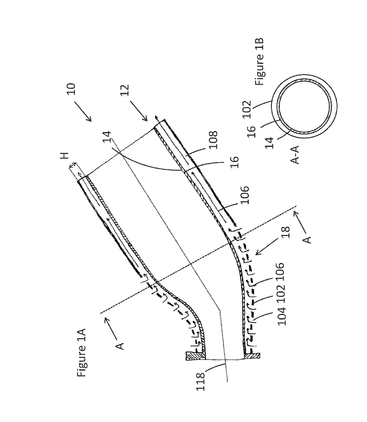
[0030]FIG. 1A shows a gas turbine combustor 10. A hot gas wall 12 has a wall part 13 comprising a front side 14 and a back side 16, along with a curved section 18. The front side 14 of the wall part is for exposure to a hot fluid. The other features of the hot gas wall 12 are not shown in this diagram.

[0031]The curved section 18 of the hot gas wall 12 is curved in two different directions; firstly, it is curved along the longitudinal direction denoted by longitudinal combustor axis 118, and secondly it is curved in the plane perpendicular to the longitudinal combustor axis as shown in FIG. 1B.

[0032]Some additional features of the gas turbine combustor are also shown, including impingement sheet 102 with cooling holes 104 and cooling fluid flow 106 (such as cooling air) along cooling channel 108.

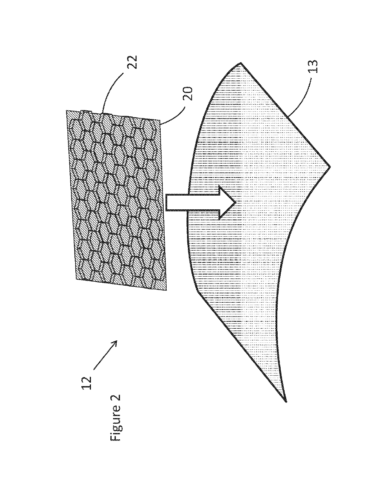
[0033]FIG. 2 shows the components of the hot gas wall 12 of FIG. 1A. A braze foil 20 (brazing sheet, also known as braze tape, braze paste or braze alloy) is placed on top of the wall part 13...


PUM

PropertyMeasurementUnit
angleaaaaaaaaaa
αaaaaaaaaaa
αaaaaaaaaaa

Abstract

A method of manufacturing a hot gas wall for a gas turbine is described. The method is carried out on a hot gas wall having a wall part with a front side and a back side, the wall part being for exposure to a hot fluid on the front side, and the hot gas wall also having a turbulator structure. In an exemplary embodiment, a turbulator structure is attached to the wall by placing a braze foil on the back side of the wall part, placing a turbulator structure on the braze foil, and brazing to attach the turbulator structure to the wall part. In another embodiment, the turbulator structure is attached by passing a current through the turbulator structure part and the wall part to resistance weld the turbulator structure part to the wall part.

Description

TECHNICAL FIELD[0001]This invention relates to methods and apparatus for cooling a hot gas wall, and particularly to methods and apparatus for attaching turbulator structures to the back side of a wall part of a hot gas wall.BACKGROUND OF THE INVENTION[0002]Gas turbine combustors use sequential liner cooling to cool the back side of hot gas walls with impingement cooling or convective cooling. Cooling features such as turbulators may be provided on the back side of these hot gas walls, but these cooling features must be cast or milled out of a solid piece of metal. This is extremely time consuming, and makes providing turbulators on the back side of hot gas walls prohibitively expensive. It also limits the placement and shape of the turbulators, and existing solutions only provide straight cooling ribs on the cylindrical part of sequential liners.SUMMARY OF THE INVENTION[0003]According to a first aspect of the invention, there is provided a method of manufacturing a hot gas wall for...

Claims


Application Information

Patent Timeline
Patent Type & Authority Patents(United States)
IPC IPC(8): F23R3/00F02C7/16F01D25/12B23K1/00B23K11/11
CPCF23R3/002B23K11/115F01D25/12F02C7/16F23R3/005B23K1/0004F23R2900/03045F05D2220/32F05D2230/237F05D2230/238F05D2240/35F05D2250/183F05D2250/283F05D2260/20F05D2260/201F05D2260/2212F05D2260/22141F23R2900/00017F23R2900/00018F23R3/60F23R2900/03043
Inventor MAURER, MICHAEL THOMASDE JONGE, JEFFREYSOBOL, KAROLINA KRYSTYNA
Owner ANSALDO ENERGIA SWITZERLAND AG
Why Eureka
Try Eureka