Vented degas bottle for motor vehicle coolant system

a technology of cooling system and venting bottle, which is applied in the direction of liquid degasification, machine/engine, separation process, etc., can solve the problems of reducing affecting the cooling efficiency of the cooling system, so as to facilitate convective cooling and inhibit the formation of air bubbles

Active Publication Date: 2022-02-15
NOVARES US ENGINE COMPONENTS INC
View PDF11 Cites 0 Cited by
  • Summary
  • Abstract
  • Description
  • Claims
  • Application Information

AI Technical Summary

Benefits of technology

[0007]It is an aspect of the present disclosure to provide an improved degas bottle that inhibits the formation of air bubbles due to turbulence, that facilitates convective cooling after engine shutdown, and that effectively separates gasses from liquid coolant thereby contributing to proper venting of the gasses from the coolant system.

Problems solved by technology

The presence of gasses within the coolant system is generally undesirable, as gasses tend to reduce the cooling efficiency of the coolant system.
The presence of gasses in the coolant system not only affects cooling efficiencies in normal coolant circulation during engine run conditions, but can also impact cooling efficiencies after engine shutdown as a result of the coolant pump shutting down, which can delay engine cooling, and even cause temperature spikes after the engine is turned off.
However, degas bottles have proven to have inefficiencies in that gas bubbles can be generated or retained therein, such as via turbulence created by coolant as it enters and flows through the degas bottle.
Further yet, known degas bottles can inhibit convective cooling, sometime referred to as thermosiphon cooling, by preventing the inlet of gasses through an inlet of the bottle after engine shutdown, thereby contributing to cooling inefficiencies after shut down, as discussed above.

Method used


Image

  • Vented degas bottle for motor vehicle coolant system
  • Vented degas bottle for motor vehicle coolant system
  • Vented degas bottle for motor vehicle coolant system

Examples


Embodiment Construction

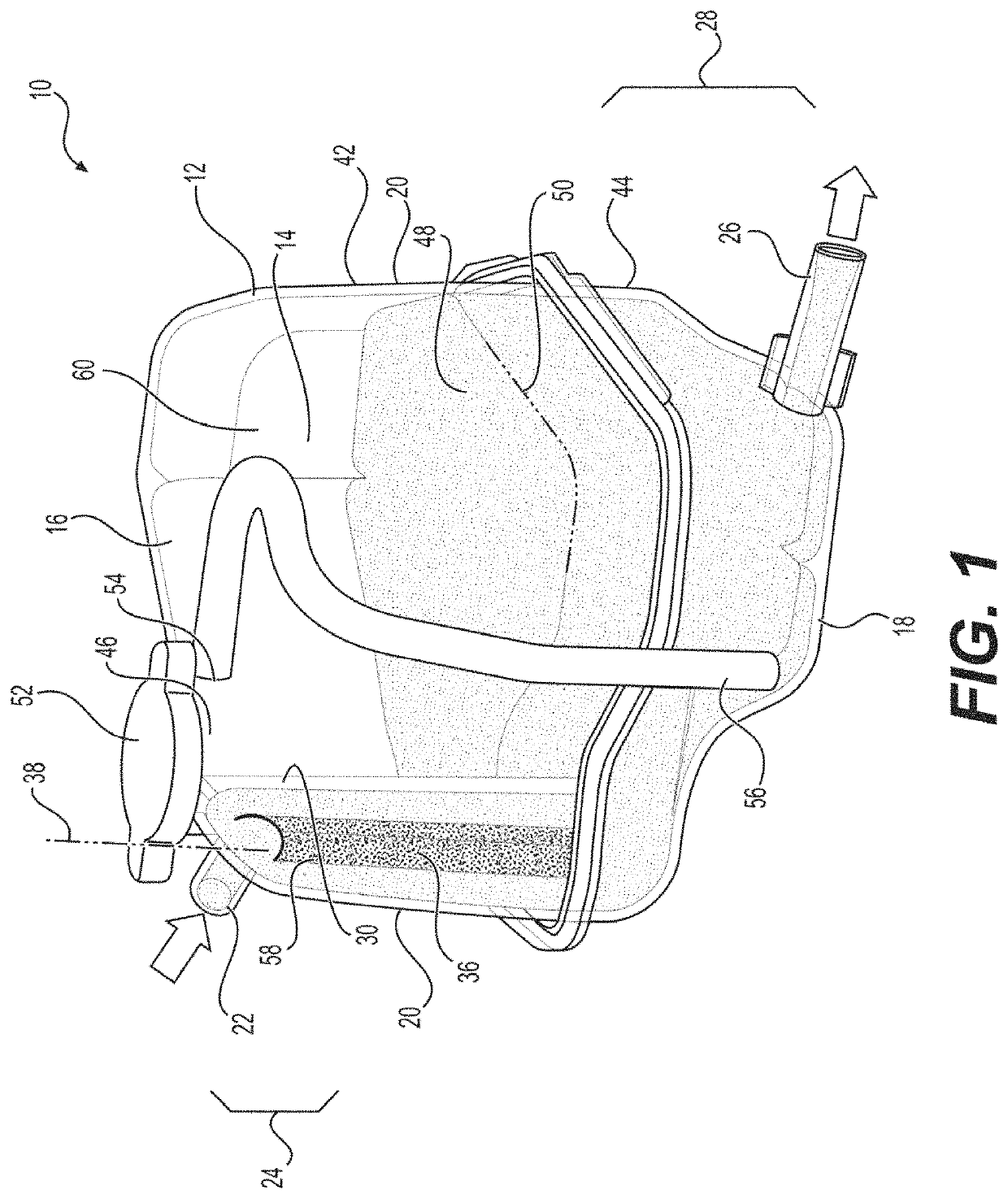
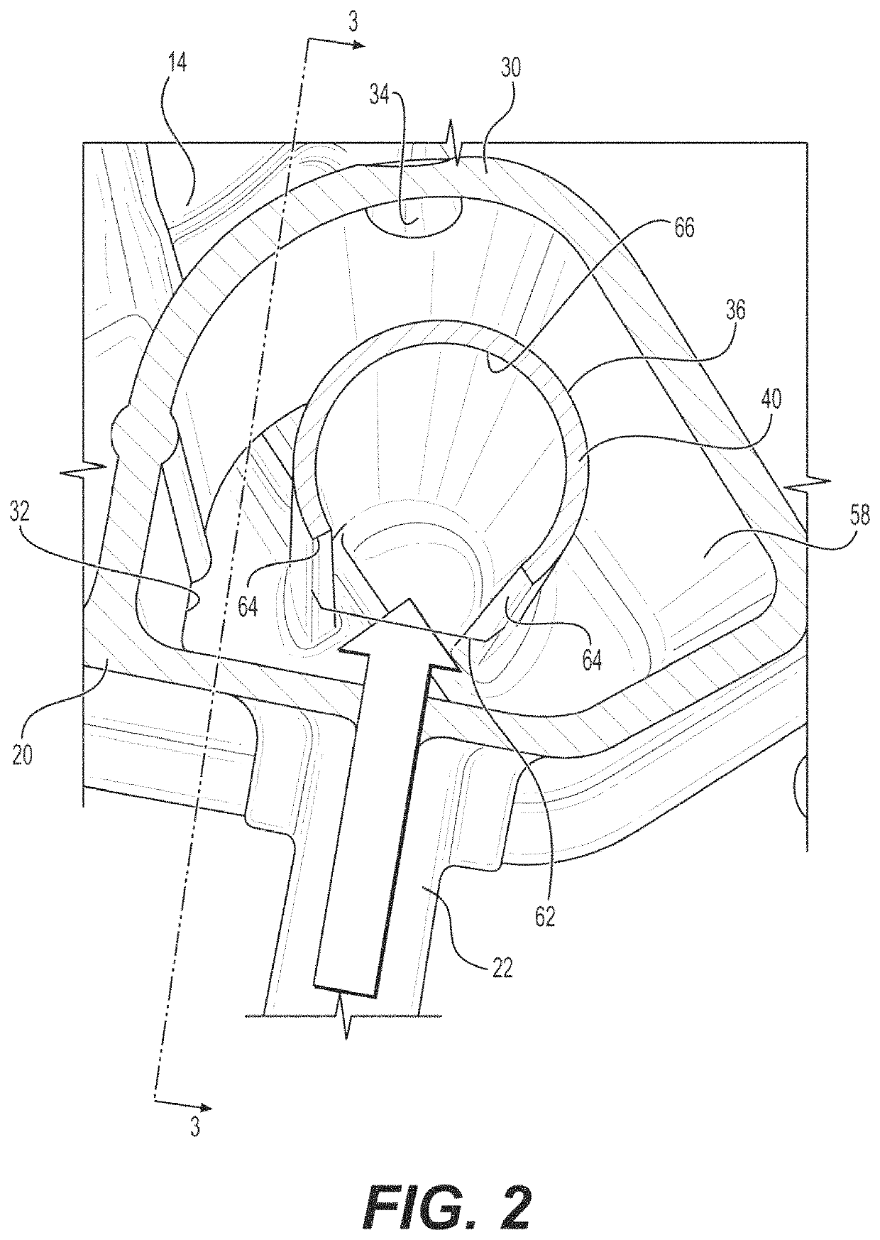
[0026]Referring in general to all of the Figures, the present disclosure and teachings described herein are directed to degas bottles and to coolant systems of motor vehicles therewith. While disclosed in accordance with one or more specific exemplary constructions, a degas bottle, wherein a first embodiment is identified by reference numeral 10 herein, may be configured other than as expressly shown and described. The inventive concepts disclosed herein are generally directed to an improved degas bottle for facilitating convective heat transfer (thermosiphon cooling) after engine shut down; reducing kinetic energy within the degas bottle that can lead to the formation of air bubbles; enhancing the separation of fluid vapor and gasses from liquid coolant within the degas bottle, and facilitating the venting of gasses from the coolant system during engine run. Accordingly, as least some of the benefits derived from the improved degas bottle include the avoidance of elevated temperatu...


PUM

PropertyMeasurementUnit
temperatureaaaaaaaaaa
temperaturesaaaaaaaaaa
pressureaaaaaaaaaa

Abstract

A degas bottle for a motor vehicle coolant system is provided. The degas bottle has a body defining an enclosed cavity bounded by an upper wall, a lower wall and a side wall extending between said upper and lower walls. An inlet extends into an upper region of the cavity proximate the upper wall and an outlet extending outwardly from a lower region of the cavity proximate the lower wall. An interior wall is disposed in the enclosed cavity. The interior wall extends from the upper wall toward the lower wall to a free end spaced from the lower wall. The interior wall has a vent opening proximate the upper wall and extends to the side wall on opposite sides of the inlet. A baffle is disposed between the interior wall and the inlet. The baffle extends from one of the upper wall or the lower wall to a free end spaced from the other of the upper wall or the lower wall.

Description

CROSS-REFERENCE TO RELATED APPLICATION[0001]This application claims the benefit of U.S. Provisional Application Ser. No. 62 / 554,476, filed Sep. 5, 2017, which is incorporated herein by reference in its entirety.BACKGROUND1. Field of the Disclosure[0002]The present disclosure relates generally to coolant systems for internal combustion engines, and more particularly to vented degas bottles for motor vehicle coolant systems.2. Related Art[0003]This section provides background information related to the present disclosure which is not necessarily prior art.[0004]As is well known, coolant systems of most modern motor vehicles having internal combustion engines are intended to remain closed, such that the coolant within the system flows in a continuous closed circuit. It is further known that during use gasses, including air and / or vaporized coolant, can form within the closed system. The presence of gasses within the coolant system is generally undesirable, as gasses tend to reduce the ...

Claims


Application Information

Patent Timeline
Patent Type & Authority Patents(United States)
IPC IPC(8): B01D19/00F01P11/02B60K11/02
CPCB01D19/0042F01P11/028F01P11/029F01P11/0285B60K11/02F01P2050/22
Inventor KISON, ANDREWJI, SANGBONGKAHABKA, WILLIAM P.
Owner NOVARES US ENGINE COMPONENTS INC
Why Eureka
Try Eureka