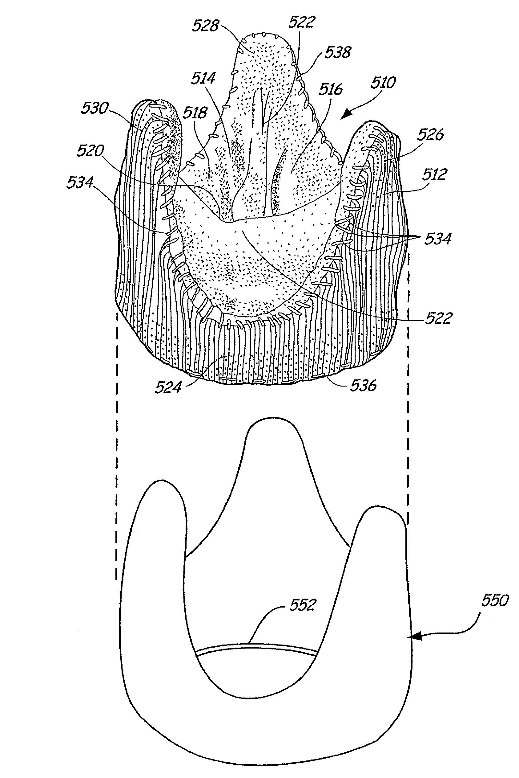
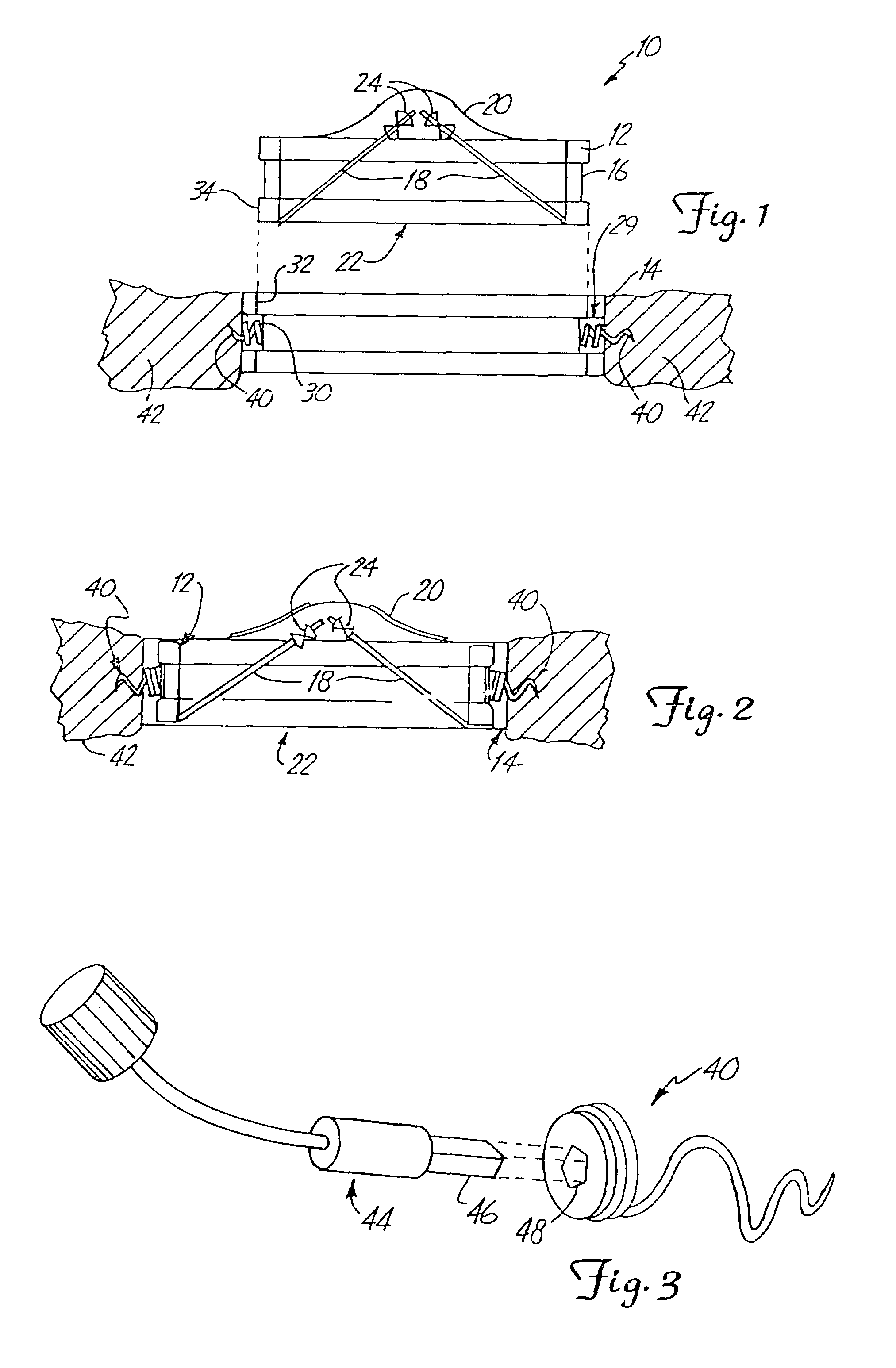
Two piece bioprosthetic heart valve with matching outer frame and inner valve

a heart valve and bioprosthetic technology, applied in the field of driver tools, can solve the problems of difficult manufacturing, labor-intensive sewing cuffs, and difficult to secure to the valve orifi

Inactive Publication Date: 2010-05-25
ST JUDE MEDICAL
View PDF73 Cites 21 Cited by
  • Summary
  • Abstract
  • Description
  • Claims
  • Application Information

AI Technical Summary

Problems solved by technology

Sewing cuffs are labor intensive, difficult to manufacture and may be difficult to secure to the valve orifice.
Further, attaching the suture cuff to the tissue annulus is time consuming and cumbersome.
The complexity of suturing requires a patient to be on cardiopulmonary bypass for a lengthy period.
However, the rings are not locked together and may become unscrewed after extended use.
However, the use of suturing is time consuming and increases the duration of the implantation surgical procedure.
However, access one at a time to the multiple helical fasteners used with an implant can be difficult and time consuming.

Method used


Image

  • Two piece bioprosthetic heart valve with matching outer frame and inner valve
  • Two piece bioprosthetic heart valve with matching outer frame and inner valve
  • Two piece bioprosthetic heart valve with matching outer frame and inner valve

Examples


embodiment 300

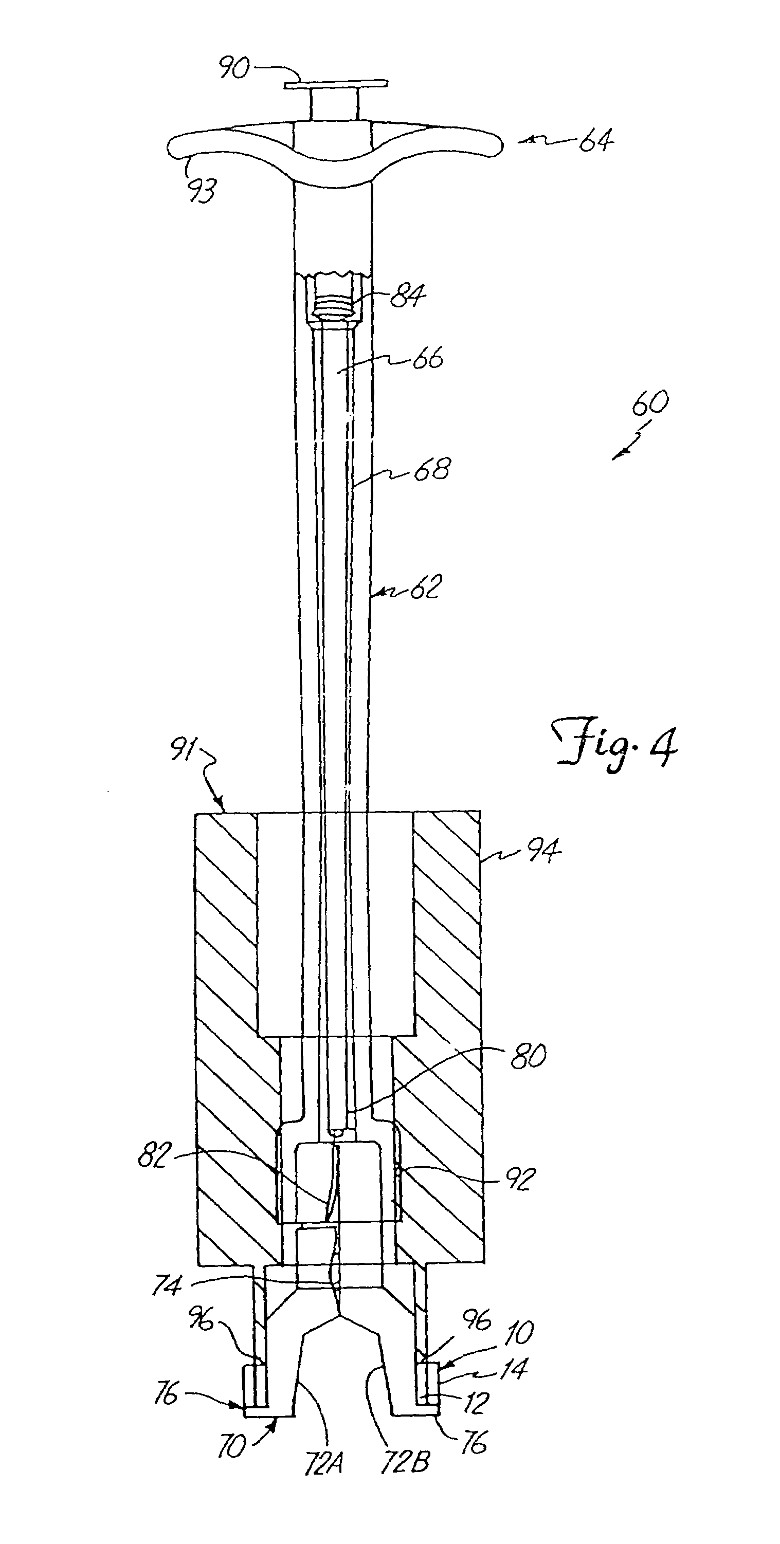
[0054]In FIGS. 15 and 16, an alternative embodiment 300 of the distal end of the driver tool shown in FIGS. 10 and 11 is shown. In FIG. 15, drive shaft 322, corresponding to drive shaft 222 in FIGS. 10 and 11, has a tapered portion 302 and a splined tip 304 at the distal end. The splined tip 304 engages a central hub 306 of a turntable 308 for rotating the turntable 308. Turntable 308 has a circular gear rack 310 spaced radially outward from the central hub 306. A plurality of spur gears 312 engage the circular gear rack 310 with loose tolerances, allowing for any misalignment between the spur gears 312 and the turntable. Each spur gear 312 has a hub 314 surrounding a throughhole 316 along a central axis of spur gear 312. Each hub 314 is flared or swaged outwardly to secure it to mounting tube 318 such that it is free to spin when driven by circular gear rack 310. Turntable 308 is free to spin in a circular groove 309 formed on the end of mounting tube 318. Each throughhole 316 is s...

embodiment 350

[0056]In FIG. 17, a further embodiment 350 is shown which is similar to the embodiment shown in FIGS. 15-16, except that the gears 352 are beveled gears and the circular gear rack 354 is correspondingly beveled to engage the beveled gears 352. Parts in FIG. 17 which are similar to those in FIGS. 15-16 have the same reference numbers that are used in FIGS. 15-16.

[0057]In the embodiments shown in FIG. 17, the springs 330 can be assisted by additional coil springs secured at location 331, if desired.

[0058]In FIG. 18, a further preferred embodiment of a helical screw fastener 400 is shown, and a corresponding driver tip 402 is shown in FIG. 1.9. Helical screw fastener 400 has a hub 404 which includes a last coil which turns into the center of helical screw fastener 400 to form a drive lug 406 which can receive a torsional force. Helical screw fastener 400 has a helical main body 408 ending in a sharp point 410 for engaging a tissue annulus such as tissue annulus 213 of FIG. 12. The driv...


PUM


Abstract

A bioprosthetic heart valve includes an outer frame configured to attach to a tissue annulus of a heart and an inner bioprosthetic valve having an exterior shape which substantially matches an interior shape of the outer frame. The exterior shape of the inner valve mates in substantial alignment with the interior shape of the outer frame. An outer frame-inner valve attachment mechanism is configured to couple the inner valve to the outer frame.

Description

CROSS-REFERENCE TO RELATED APPLICATION[0001]This application is a continuation-in-part of application Ser. No. 09 / 203,169, filed Dec. 1, 1998, now U.S. Pat. No. 6,074,418, and entitled “DRIVER TOOL FOR HEART VALVE PROSTHESIS FASTENERS”, which is a continuation-in-part of application Ser. No. 09 / 062,822, filed Apr. 20, 1998, now U.S. Pat. No. 6,176,877, and titled “TWO PIECE PROSTHETIC HEART VALVE.”FIELD OF THE INVENTION[0002]The present invention relates to mechanical heart valve prostheses. More specifically, the invention relates to a driver tool for attaching and implanting heart valve prostheses.BACKGROUND OF THE INVENTION[0003]Implantable mechanical heart valves are used for replacement of defective valves in hearts of patients. One common method employs a sewing ring or suture cuff which is attached to and extends around the outer circumference of the mechanical valve orifice. The sewing cuff is made of a biocompatible fabric suitable for allowing a needle and suture to pass t...

Claims


Application Information

Patent Timeline
Patent Type & Authority Patents(United States)
IPC IPC(8): A61F2/24
CPCA61B17/068A61F2/2427A61F2/2412A61B2017/0648
Inventor BUCHANAN, ERIC S.
Owner ST JUDE MEDICAL
Why Eureka
Try Eureka