Method and apparatus for replacing a mitral valve with a stentless bioprosthetic valve

a bioprosthetic valve and native technology, applied in the field of method and apparatus for replacing a native mitral valve with a stentless bioprosthetic valve, can solve the problems of many additional problems that patients face, high cardiac output imposed by a smaller size artificial valve, and the inability to perform mitral valve surgery

Inactive Publication Date: 2006-08-31
THE CLEVELAND CLINIC FOUND
View PDF21 Cites 14 Cited by
  • Summary
  • Abstract
  • Description
  • Claims
  • Application Information

AI Technical Summary

Benefits of technology

[0015] The conduit further includes first and second leaflets that mimic the three dimensional anatomical shape of the anterior and posterior leaflets of the native mitral valve. The first and second leaflets extend between the proximal end and the distal end of the conduit. The distal end of the conduit defines a second annulus, which has a profile which is substantially similar to a profile of said first annulus, and at which the first and second leaflets terminate. The distal end of the conduit does not include bioprosthetic chordae tendineae. The second annulus is configured to be sutured to the ring formed by the free edges of the anterior and posterior leaflets at the distal end of the native mitral valve that remain intact following resection of the native mitral valve so that the native chordae tendineae, which are attached to the papillary muscles, continue to provide prolapse prevention and left ventricular muscle support functions in addition to maintaining the continuity between the valve annulus and the papillary muscles. The entire circumference of the second annulus formed at the distal end by the first and second leaflets is spaced from the papillary muscles.

Problems solved by technology

Reparative techniques to correct mitral valve disease are often the best surgical approach for dealing with mitral valve abnormalities, however, mitral valvuloplasty is not always feasible because of extensive fibrosis, leaflets calcification, or massive chordal rupture.
However, there are many additional problems that face patients after valve replacement with a prosthetic valve.
Valve-related problems include limitation of the mitral flow (due to a small effective orifice area) during exercise and high cardiac output imposed by a smaller size artificial valve as compared with the natural valve orifice area.
Myocardial rupture, a lethal complication of mitral valve replacement, results from excision or stretching of the papillary muscle in a thin and fragile left ventricle.
Also, the difficulties in controlling adequate anticoagulation for a mechanical valve bring a high morbidity risk factor of thromboembolic and hemorrhagic complication and endocarditis.
Stented tissue valves, although less thrombogenic, are not reliably durable and, because of the rigid stent, they are less hemodynamically efficient.
However, stentless mitral valves are not yet commonly available for clinical use because of the anatomical and functional complexity of the mitral valve and the subvalvular apparatus, resulting in the difficulties of the design and implantation procedures of the stentless mitral valves.

Method used


Image

  • Method and apparatus for replacing a mitral valve with a stentless bioprosthetic valve
  • Method and apparatus for replacing a mitral valve with a stentless bioprosthetic valve
  • Method and apparatus for replacing a mitral valve with a stentless bioprosthetic valve

Examples


first embodiment

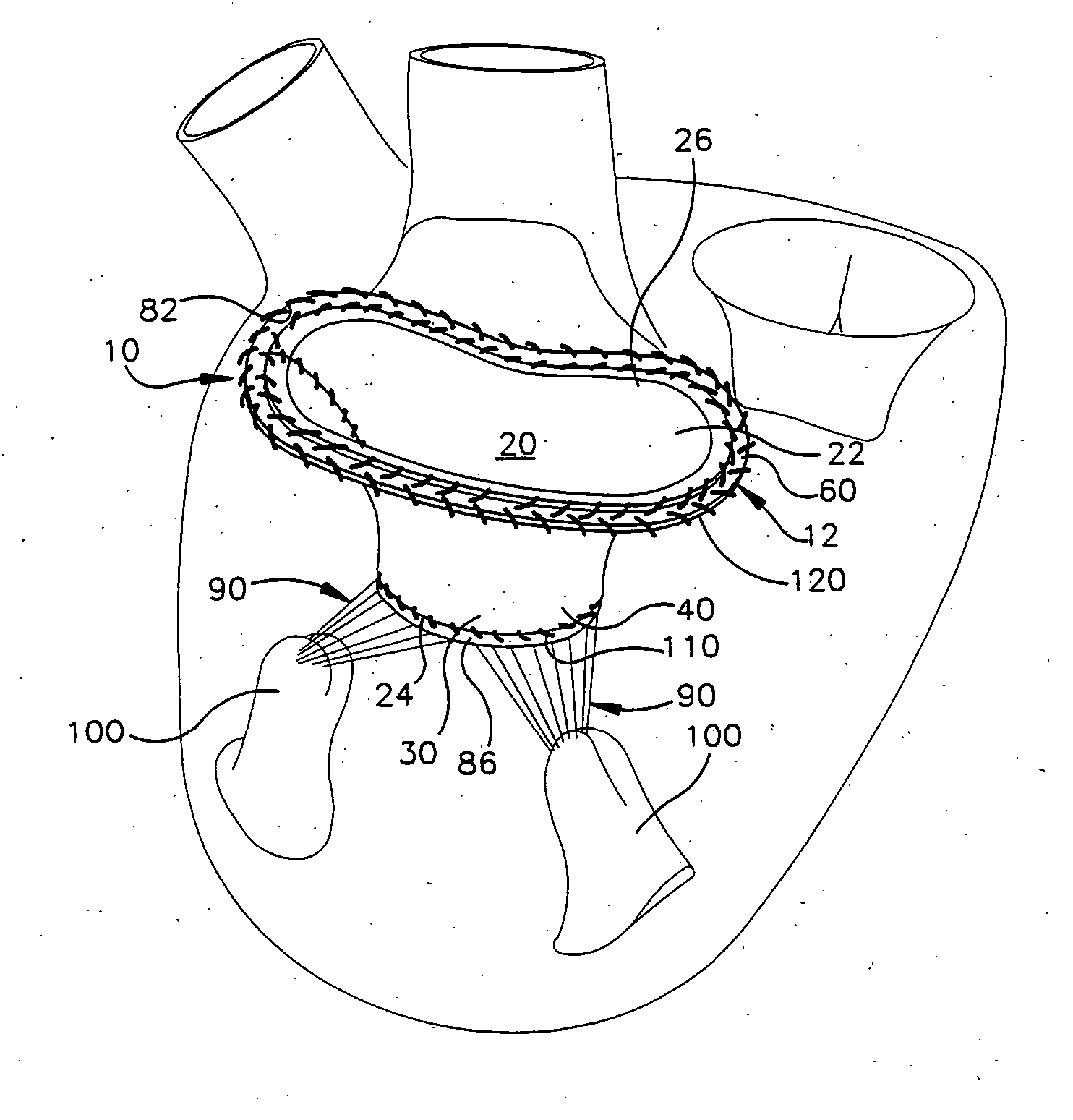
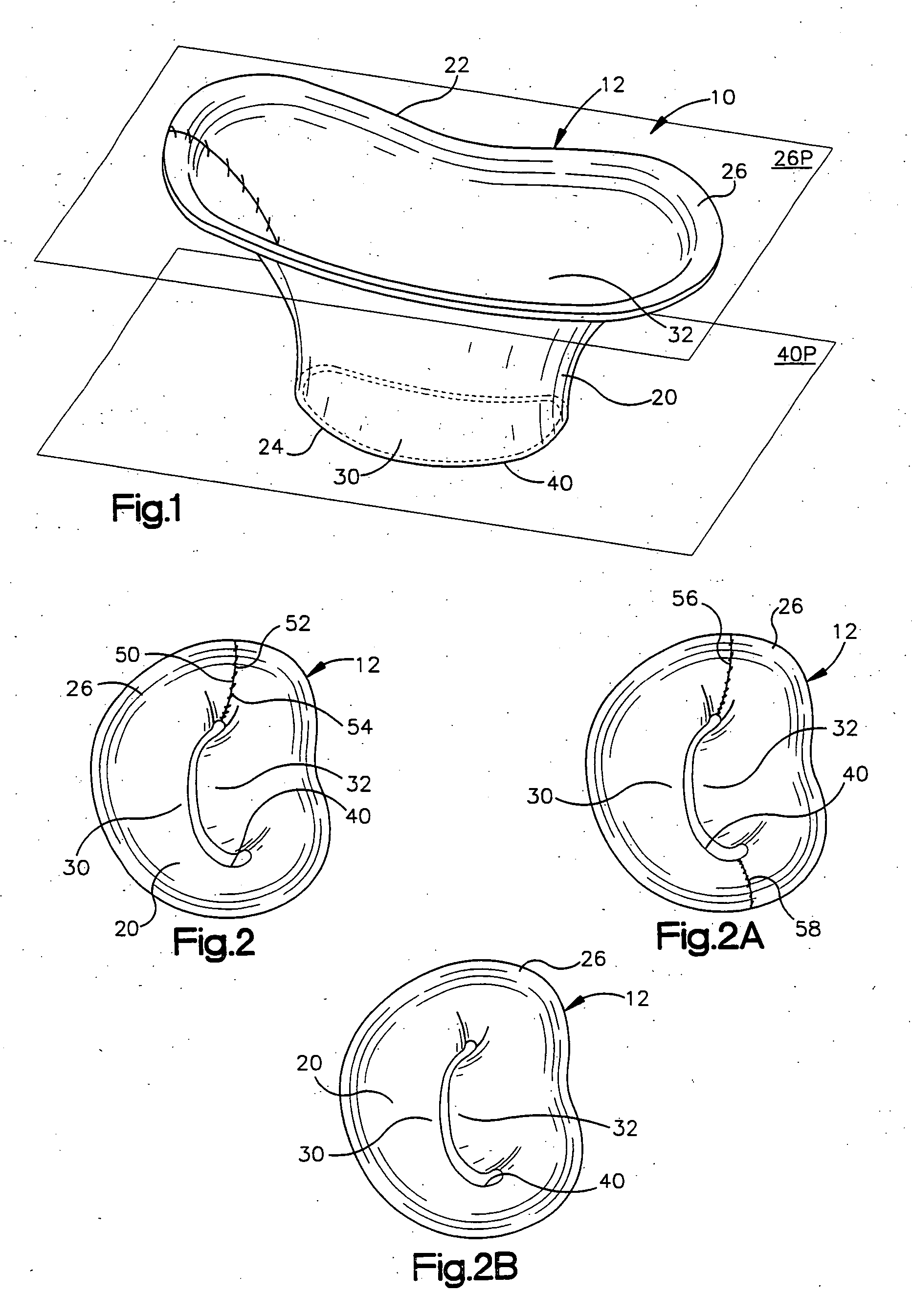
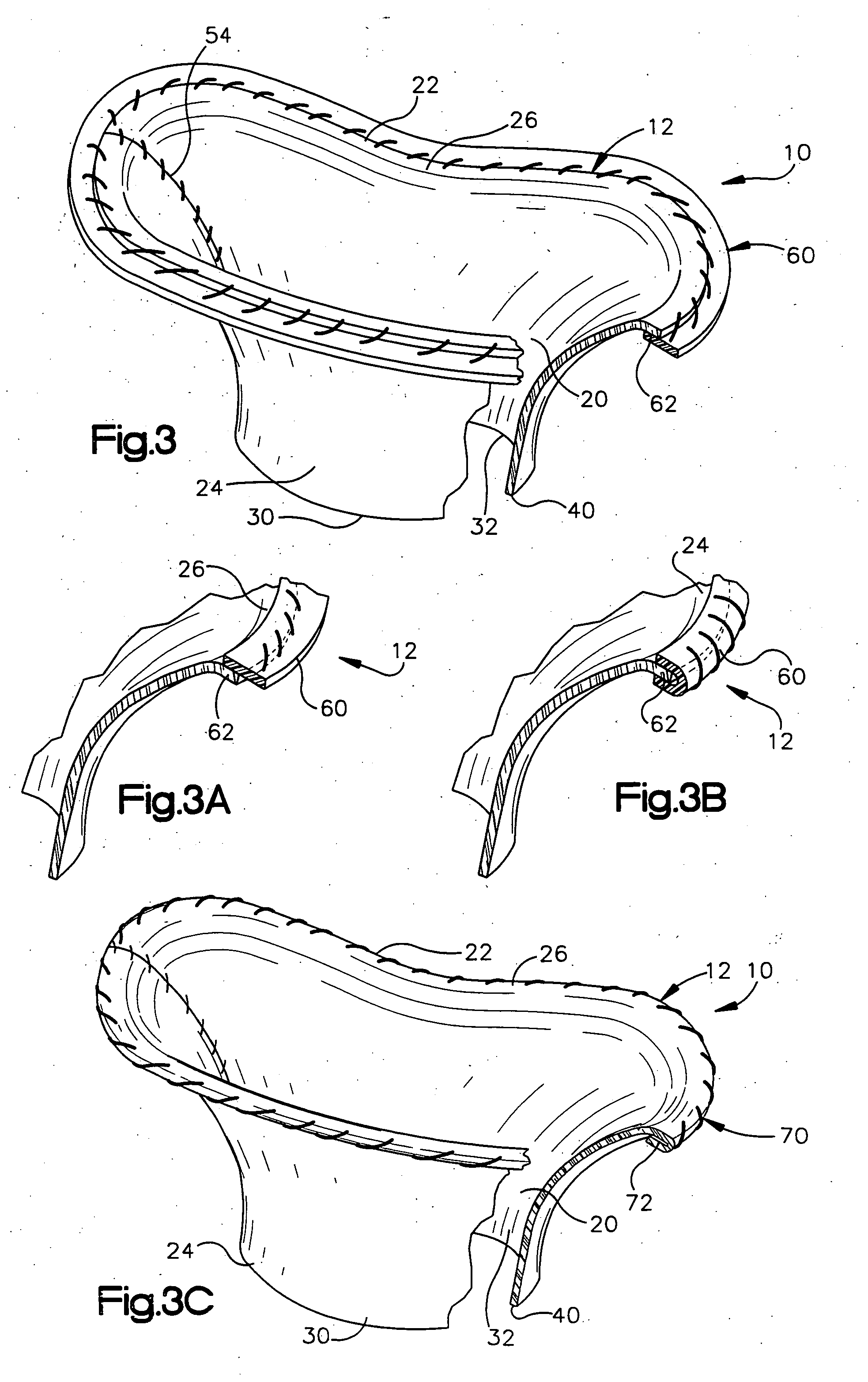
[0047] The present invention relates to a method and apparatus for replacing a native mitral valve with a stentless bioprosthetic valve. As representative of the present invention, FIG. 1 illustrates an apparatus 10 comprising a stentless bioprosthetic valve 12 for replacing a native mitral valve 14 (FIG. 4) of a human patient in accordance with a However, the depiction of the bioprosthetic valve 12 in FIGS. 1-10 is merely representative of the relative arrangements of elements of exemplary embodiments of the present invention. These Figures are not drawn to scale and do not restrict relative scales or dimensions of elements of the present invention or application of the present invention to any patient in a desired manner.

[0048] The bioprosthetic valve 12 shown in FIG. 1 is made from one or more pieces of biocompatible material formed into a bi-leaflet conduit 20 having dimensions that correspond to the dimensions of the native mitral valve 14. The conduit 20 has a proximal end 22...

second embodiment

[0070]FIGS. 8-10 illustrate an apparatus 10′ comprising a stentless bioprosthetic valve 12′ in accordance with the present invention in which the bioprosthetic valve comprises a homograft mitral valve. In FIGS. 8-10, reference numbers that are the same as those used in FIGS. 1-7 indicate structure that is the same as described above for the previous embodiment, while reference numbers that have apostrophe (') indicate similar, but not identical, structure.

[0071] In accordance with the second embodiment, the homograft valve 12′ to be implanted must be harvested. To harvest the valve 12′, the left atrium of the donor heart is opened and the mitral valve annulus 82, the leaflets 30′ and 32′, and the subvalvular tissues (the chordae tendineae 90 and the papillary muscles 100) are anatomically evaluated. The valve 12′, and in particular the heights of the leaflets 30′ and 32′, are measured.

[0072] The left ventricle is then opened and the entire valve 12′ is excised or removed by incisio...


PUM


Abstract

A stentless bioprosthetic valve includes at least one piece of biocompatible material comprising a bi-leaflet conduit. The conduit has a distal end, a proximal end defining a first annulus for suturing to the valve annulus of a heart, and leaflets extending between the proximal and distal ends. The distal end defines a second annulus having a profile substantially similar to a first annulus profile, at which the leaflets terminate. The second annulus is sutured to free edges of the leaflets of the native mitral valve that remain intact following resection of the native mitral valve. Therefore, the native chordae tendineae continue to provide prolapse prevention and left ventricular muscle support functions in addition to maintaining continuity between the valve annulus and the papillary muscles. The second annulus is spaced from the papillary muscles. A method for replacing the native mitral valve with a stentless bioprosthetic valve is also provided.

Description

RELATED APPLICATION [0001] This application is a continuation-in-part of copending patent application Ser. No. 10 / 683,105, filed Oct. 10, 2003, which claims priority from U.S. provisional patent application Ser. No. 60 / 417,912, filed Oct. 10, 2002, the subject matter of which is incorporated herein by reference.TECHNICAL FIELD [0002] The present invention relates to a method and apparatus for replacing a native mitral valve with a stentless bioprosthetic valve. BACKGROUND OF THE INVENTION [0003] The mitral valve is a functional unit composed of multiple dynamically interrelated units. During cardiac cycle, the fibrous skeleton, the anterior and posterior leaflets, the papillary muscles, the chordae tendineae, and the ventricular and atrial walls all interplay symphonically to render a competent valve. The complex interaction between the mitral valve and the ventricle by the subvalvular apparatus (the papillary muscles and the chordae tendineae) is essential in that it maintains the ...

Claims


Application Information

Patent Timeline
Patent Type & Authority Applications(United States)
IPC IPC(8): A61F2/24
CPCA61F2/2412A61F2220/0075A61F2/2457
Inventor NAVIA, JOSE L.NAVIA, JOSE A.JORDANA, JORGE LUIS
Owner THE CLEVELAND CLINIC FOUND
Why Eureka
Try Eureka