Method and apparatus for replacing a mitral valve with a stentless bioprosthetic valve

a bioprosthetic valve and native technology, applied in the field of method and apparatus for replacing a native mitral valve with a stentless bioprosthetic valve, can solve the problems of many additional problems, high cardiac output imposed by a smaller size artificial valve, and the inability to perform mitral valve surgery. achieve the effect of preventing dilatation of the valve and maintaining continuity

Active Publication Date: 2006-08-08
THE CLEVELAND CLINIC FOUND
View PDF19 Cites 13 Cited by
  • Summary
  • Abstract
  • Description
  • Claims
  • Application Information

AI Technical Summary

Benefits of technology

[0019]In accordance with another feature of the invention, the bioprosthetic valve further comprises a biocompatible, unstented ring connected to the first annulus for supporting the first annulus and for suturing to the valve annulus of the heart. The ring, when sutured to the valve annulus, impedes dilatation of the valve annulus and preserves motion of the valve annulus.
[0020]The present invention also provides a method for replacing a native mitral valve having anterior and posterior leaflets with a stentless bioprosthetic valve. According to the inventive method, at least one piece of biocompatible material that comprises a bi-leaflet conduit having dimensions that correspond to the dimensions of the native mitral valve being replaced is provided. The conduit has a proximal end and a distal end. The proximal end defines a first annulus and the distal end defines a second annulus. The conduit further includes first and second leaflets that mimic the three-dimensional shape of the anterior and posterior leaflets of the native mitral valve. The first and second leaflets extend from the proximal end and terminate at the distal end of the conduit. The majority of the anterior a

Problems solved by technology

Reparative techniques to correct mitral valve disease are often the best surgical approach for dealing with mitral valve abnormalities, however mitral valvuloplasty is not always feasible because of extensive fibrosis, leaflets calcification, or massive chordal rupture.
However, there are many additional problems that face patients after valve replacement with a prosthestic valve.
Valve-related problems include limitation of the mitral flow (due to a small effective orifice area) during exercise and high cardiac output imposed by a smaller size artificial valve as compared with the natural valve orifice area.
Myocardial rupture, a lethal complication of mitral valve replacement, results from exc

Method used


Image

  • Method and apparatus for replacing a mitral valve with a stentless bioprosthetic valve
  • Method and apparatus for replacing a mitral valve with a stentless bioprosthetic valve
  • Method and apparatus for replacing a mitral valve with a stentless bioprosthetic valve

Examples


first embodiment

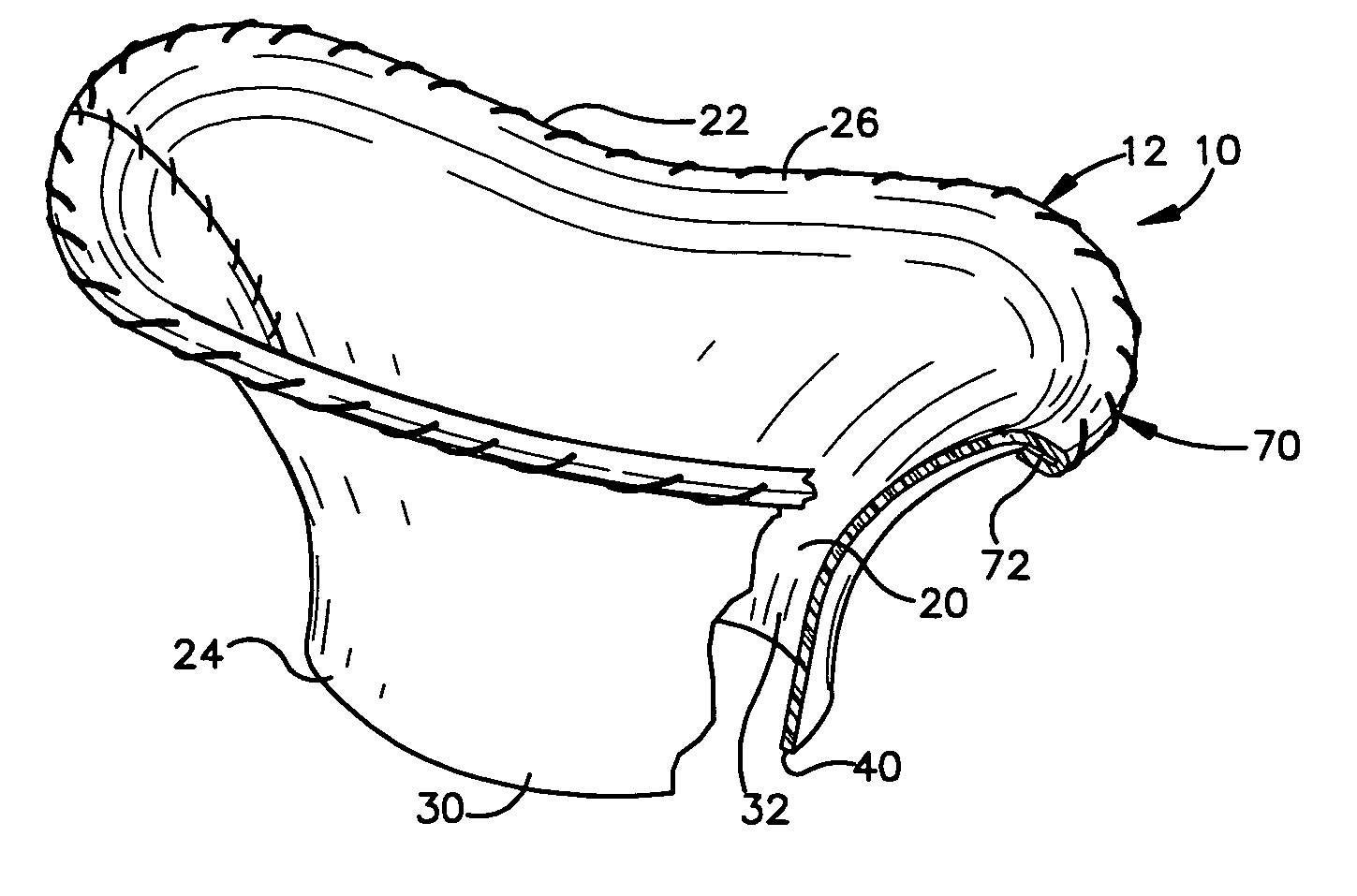
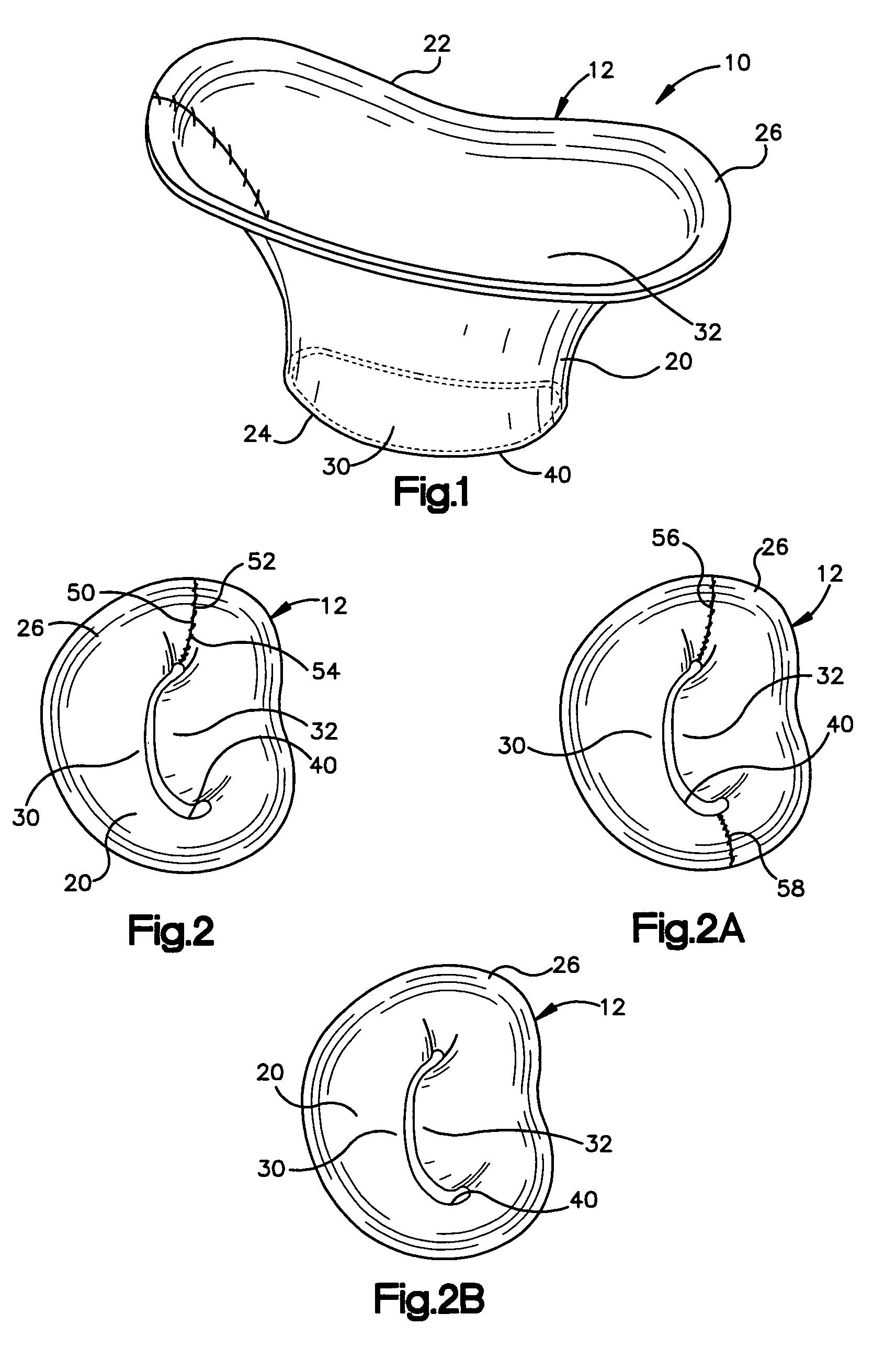
[0038]The present invention relates to a method and apparatus for replacing a native mitral valve with a stentless bioprosthetic valve. As representative of the present invention, FIG. 1 illustrates an apparatus 10 comprising a stentless bioprosthetic valve 12 for replacing a native mitral valve 14 (FIG. 4) in accordance with a

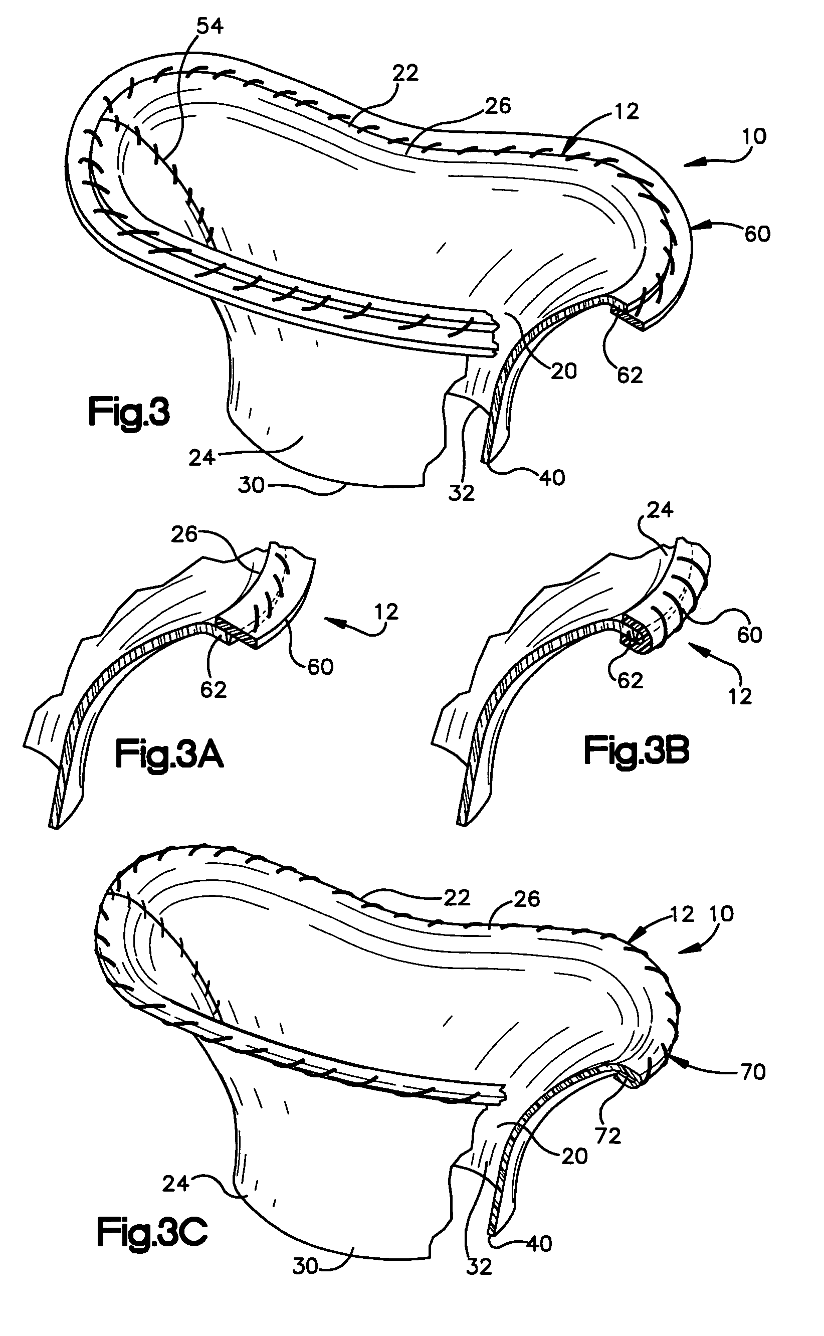
[0039]The bioprosthetic valve 12 shown in FIG. 1 is made from one or more pieces of biocompatible material formed into a bi-leaflet conduit 20 having dimensions that correspond to the dimensions of the native mitral valve 14. The conduit 20 has a proximal end 22 and a distal end 24. The proximal end 22 defines a first annulus 26 for suturing to the valve annulus of the native mitral valve 14, as described further below.

[0040]The conduit 20 further includes first and second leaflets 30 and 32 (FIG. 2) that mimic the three-dimensional anatomical shape of the anterior and posterior leaflets 34 and 36 (FIG. 4), respectively, of the native mitral valve 14. The firs...

second embodiment

[0059]FIGS. 8–10 illustrate an apparatus 10′ comprising a stentless bioprosthetic valve 12′ in accordance with the present invention in which the bioprosthetic valve comprises a homograft mitral valve. In FIGS. 8–10, reference numbers that are the same as those used in FIGS. 1–7 indicate structure that is the same as described above for the previous embodiment, while reference numbers that have apostrophe (′) indicate similar, but not identical, structure.

[0060]In accordance with the second embodiment, the homograft valve 12′ to be implanted must be harvested. To harvest the valve 12′, the left atrium of the donor heart is opened and the mitral valve annulus 82, the leaflets 30′ and 32′, and the subvalvular tissues (the chordae tendineae 90 and the papillary muscles 100) are anatomically evaluated. The valve 12′, and in particular the heights of the leaflets 30′ and 32′, are measured.

[0061]The left ventricle is then opened and the entire valve 12′ is excised or removed by incision o...


PUM


Abstract

A stentless bioprosthetic valve includes at least one piece of biocompatible material comprising a bi-leaflet conduit. The conduit has a distal end and a proximal end that defines a first annulus for suturing to the valve annulus of a heart. The conduit further includes first and second leaflets that mimic the anterior and posterior leaflets of the native mitral valve. The first and second leaflets extend between the proximal and distal ends. The distal end defines a second annulus at which the first and second leaflets terminate. The second annulus is for suturing to free edges of the anterior and posterior leaflets of the native mitral valve that remain intact following resection of the native mitral valve so that the native chordae tendineae continue to provide prolapse prevention and left ventricular muscle support functions in addition to maintaining the continuity between the valve annulus and the papillary muscles. A method for replacing the native mitral valve with a stentless bioprosthetic valve is also provided.

Description

RELATED APPLICATION[0001]This application claims priority from U.S. provisional patent application Ser. No. 60 / 417,912, filed on Oct. 10, 2002, the subject matter of which is incorporated herein by reference.TECHNICAL FIELD[0002]The present invention relates to a method and apparatus for replacing a native mitral valve with a stentless bioprosthetic valve.BACKGROUND OF THE INVENTION[0003]The mitral valve is a functional unit composed of multiple dynamically interrelated units. During cardiac cycle, the fibrous skeleton, the anterior and posterior leaflets, the papillary muscles, the chordae tendineae, and the ventricular and atrial walls all interplay symphonically to render a competent valve. The complex interaction between the mitral valve and the ventricle by the subvalvular apparatus (the papillary muscles and the chordae tendineae is essential in that it maintains the continuity between the atrio-ventricular ring (which is part of the fibrous skeleton of the heart) and the vent...

Claims


Application Information

Patent Timeline
IPC IPC(8): A61F2/24A61BA61F
CPCA61F2/2412A61F2/2457A61F2220/0075Y10S623/904
Inventor NAVIA, JOSE' LUISNAVIA, JOSE' A.JORDANA, JORGE L.
Owner THE CLEVELAND CLINIC FOUND
Why Eureka
Try Eureka