Apparatus and method for thawing biological materials

a biological material and apparatus technology, applied in the direction of flexible containers, container/bottle contruction, rigid containers, etc., can solve the problems of wasting plasma, thawed plasma has a limited shelf life, coagulant factors in thawed plasma can degrade in a relatively short amount of time, etc., to accelerate the thawing process

Inactive Publication Date: 2010-05-25
CYTOTHERM +1
View PDF20 Cites 36 Cited by
  • Summary
  • Abstract
  • Description
  • Claims
  • Application Information

AI Technical Summary

Benefits of technology

[0004]In a first aspect of the present invention, an apparatus is provided that rapidly thaws and heats biological materials, such as plasma, stored in an intravenous bag, packet or similar enclosure. The apparatus has a hollow bladder having a flexible wall that is placed in contact with the bag. A circulation system draws fluid from a reservoir and fills the bladder with the fluid. The circulation system also drains fluid from the bladder. A heater in the rese...

Problems solved by technology

Thawed plasma has a limited shelf life, and coagulant factors in thawed plasma can degrade in ...

Method used


Image

  • Apparatus and method for thawing biological materials
  • Apparatus and method for thawing biological materials
  • Apparatus and method for thawing biological materials

Examples


second embodiment

[0041]Thus far, one bladder configuration has been described in detail and illustrated. The present invention is intended to work with a number of bladder configurations, and the configuration described thus far is not the only configuration contemplated. Referring to FIGS. 8-9, the invention is shown using upper and lower bladders 130, 131 in a rack 125. The upper and lower bladders 130, 131 are placed above and below a plasma bag 121, respectively. The rack 125 has a lid 129 with a rigid projection or hub 138 that extends inwardly and bears against the upper bladder 130 when the lid is closed. The bladders 130, 131 are each connected to separate circulation pumps that are operable to expand and contract the bladders at different intervals. As in the previous embodiment, the pumps operate in a first mode and a second mode, and each bladder drains fluid to a fluid reservoir in the apparatus.

[0042]In the first mode, a first pump fills the upper bladder 130 with fluid while the lower ...

first embodiment

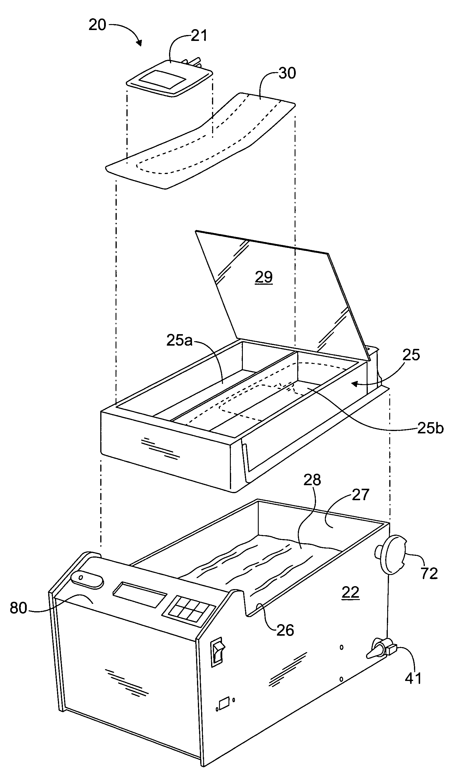
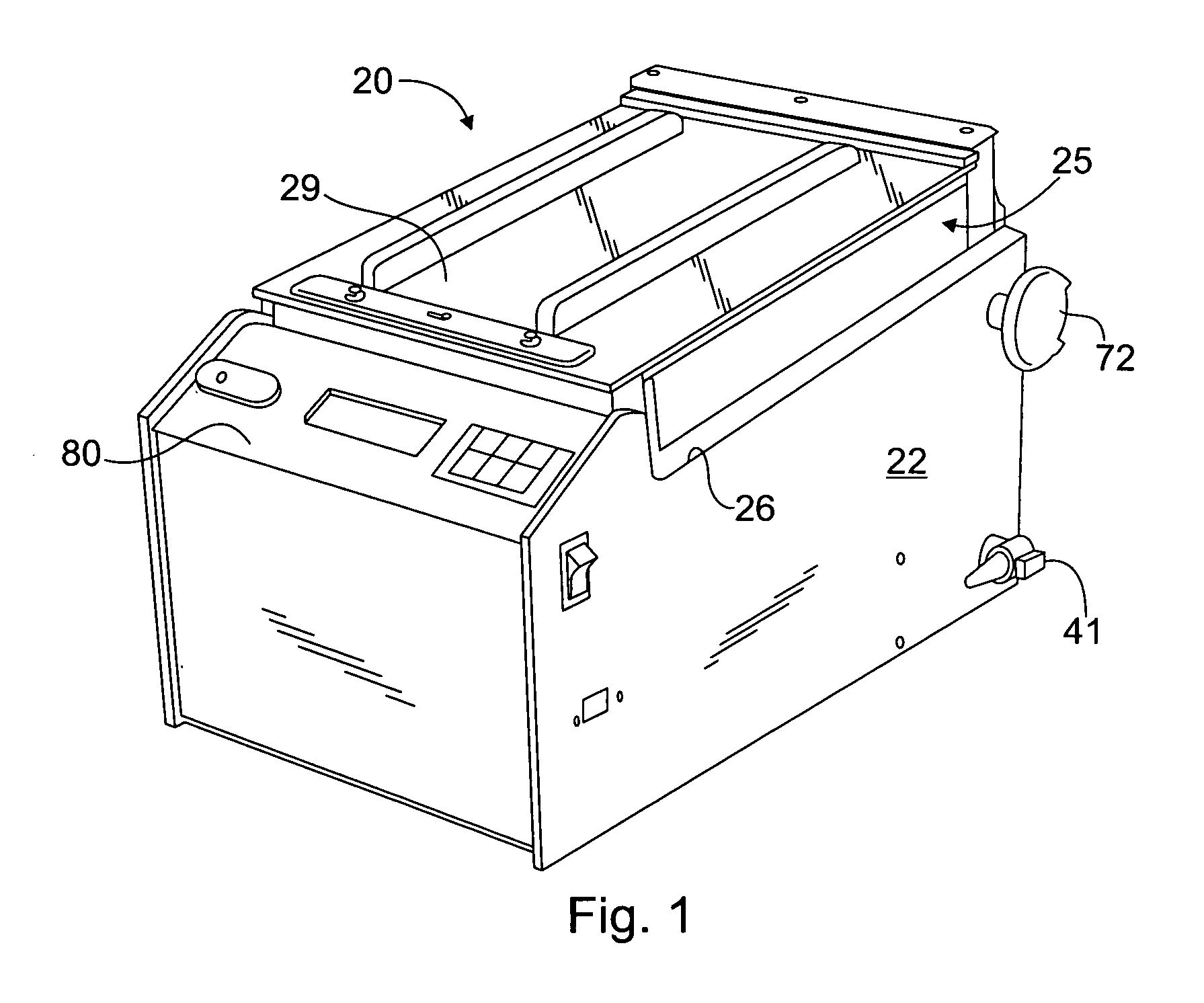
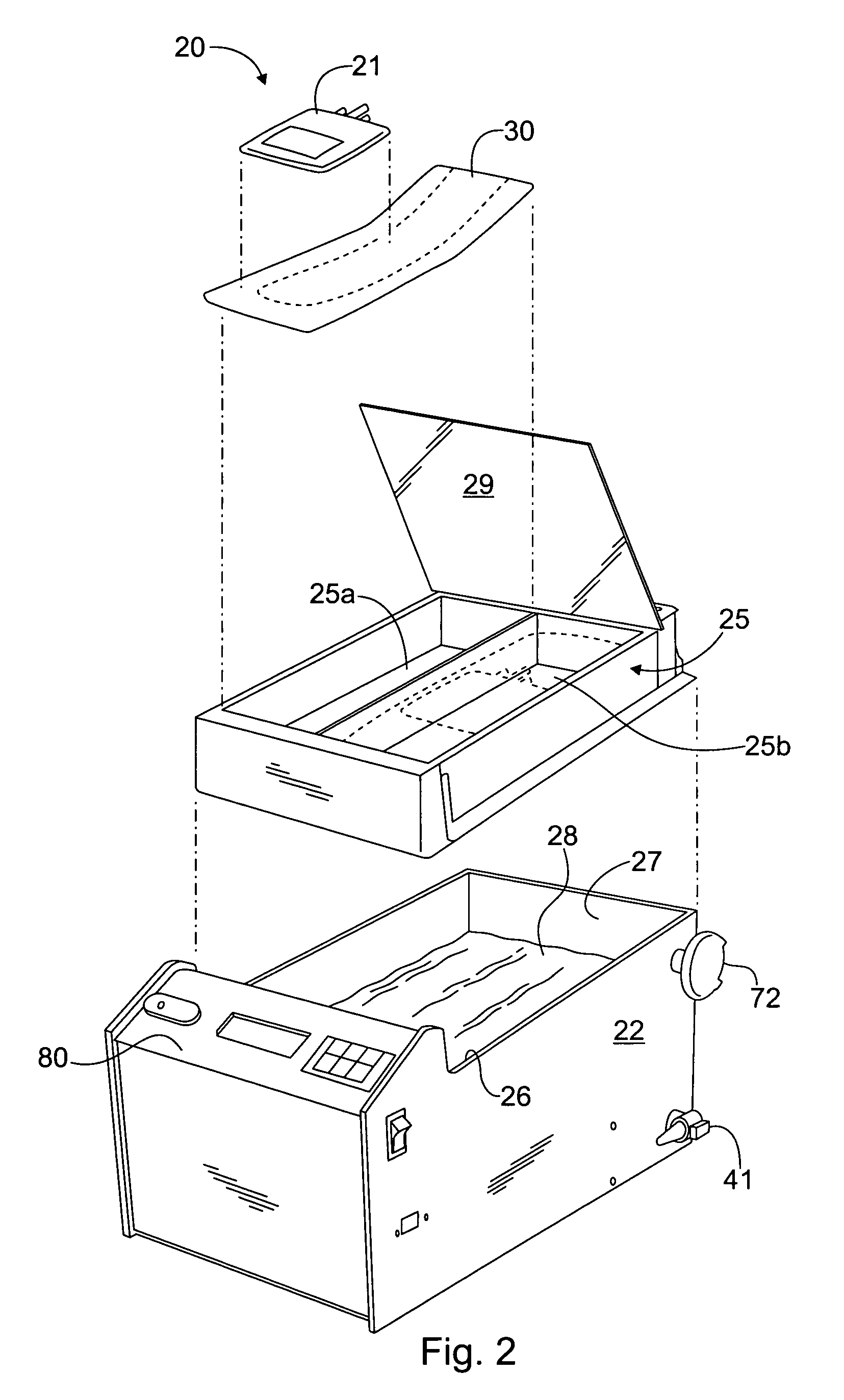
[0043]Operation of the apparatus 20 will now be described with reference to the The tank 22 is placed on a level surface, and the rack is disconnected from any conduits or tubing beneath the rack. The rack 25 is then removed from the receptacle on the top of the tank so that the top of the tank is open and the reservoir 27 is exposed. The reservoir 27 is filled with tap water, deionized water or other appropriate fluid. If deionized water is used, a source of ions, such as salt, should be added to the water to make the water conductive. In this way, the water level sensor in the reservoir 27 can monitor the water level and detect when the water level is low. If desired, a chemical additive to limit algae growth may also be added to the fluid 28.

[0044]Once the reservoir 27 is filled with fluid 28, the rack is held above the tank 22, and the conduits 46, 48 are connected to the inlet fittings 31 on the underside of the rack 25. The rack 25 is then lowered into the receptacle on the t...


PUM

PropertyMeasurementUnit
Temperatureaaaaaaaaaa
Timeaaaaaaaaaa

Abstract

An apparatus and method are provided to rapidly thaw and heat frozen bags of biological materials, such as plasma. The apparatus has a hollow bladder having a flexible wall that is placed in contact with the bag. A circulation system draws fluid from a reservoir and fills the bladder with the fluid. The circulation system also drains fluid from the bladder. A heater in the reservoir heats the fluid before the fluid enters the bladder. As heated fluid flows through the bladder, heat is transferred through the bladder wall to the plasma bag to thaw the biological material. The bladder wall expands against the plasma bag as the bladder fills with fluid, and contracts from the plasma bag as the bladder is drained. The expansion and contraction of the bladder wall agitates the plasma bag and biological material to accelerate the thawing process.

Description

RELATED APPLICATIONS[0001]This application claims priority to U.S. Provisional Application No. 60 / 328,545, filed Oct. 11, 2001, which is hereby incorporated herein by reference.FIELD OF THE INVENTION[0002]The present invention relates to apparatuses for thawing biological materials, such as plasma, and more specifically to apparatuses that thaw biological materials by agitation and heat transfer.BACKGROUND OF THE INVENTION[0003]In the present state of the art, plasma and other biological materials are stored in a frozen state to preserve the materials for subsequent use in a patient. In many cases, it is desirable to thaw frozen biological materials rapidly. For example, frozen plasma must be thawed rapidly to be used in emergency situations. Rapid thawing is also desirable to limit the amount of time that thawed plasma sits in storage. Thawed plasma has a limited shelf life, and coagulant factors in thawed plasma can degrade in a relatively short amount of time. When thawing time i...

Claims


Application Information

Patent Timeline
IPC IPC(8): B01J19/00A61F7/00B30B1/32B65D1/32C12M1/00F24J1/00B65D30/08B65B1/04A61F7/12A61M16/00B01D35/18A01N1/02F24V30/00
CPCA01N1/0242A01N1/0284
Inventor KUZYK, ROMAN
Owner CYTOTHERM
Why Eureka
Try Eureka