Container assembly for a motor vehicle

a technology for motor vehicles and containers, applied in the direction of machines/engines, mechanical equipment, transportation and packaging, etc., can solve the problems of ice pressure damage affecting, and achieve the effects of reducing load, reducing damage, and accelerating thawing process

Active Publication Date: 2019-12-17
ROBERT BOSCH GMBH
View PDF9 Cites 2 Cited by
  • Summary
  • Abstract
  • Description
  • Claims
  • Application Information

AI Technical Summary

Benefits of technology

[0007]A respective feed device (feed line) is provided on the first container and on the second container to enable the fuel or the liquid auxiliary agent, e.g. the reducing agent solution, to be introduced into the respective container. In a particularly preferred embodiment of the container assembly according to the invention, the feed device of the first container and the feed device of the second container are arranged adjacent to one another. In a preferred embodiment, a return line for fuel, in particular for heated fuel, opens into the feed device of the first container. This has the particular advantage that introducing heated fuel also heats the adjacent feed device for the second container (auxiliary agent container). It is thereby possible to accelerate the thawing process that may be required for the liquid auxiliary agent in the feed device and in the second container, thus making it possible to relieve the load on possibly electrically driven heating devices for the auxiliary agent container.
[0008]The feed device of the first container and the feed device of the second container can each be provided at the top of the containers. This embodiment is particularly advantageous since, in this case, the feed devices are very readily accessible, thus allowing the fuel or the liquid auxiliary agent to be replenished without problems.
[0009]In another preferred embodiment, the first container and the second container have at least one common wall. This embodiment is suitable particularly for embodiments in which the second container is integrated into the interior of the first container. It is thereby possible to save material in the production of the containers, this being advantageous in respect of reducing weight, for example. In other embodiments, the first container and the second container can each have an entirely separate wall structure, thereby providing advantages for assembly in some circumstances. For example, the fuel tank (first container) and the tank for the auxiliary agent (second container) can be manufactured separately, wherein the fuel tank has a suitable lateral recess for the geometrical fitting of the auxiliary agent tank, into which the auxiliary agent tank can be inserted.

Problems solved by technology

As a result, there may be ice pressure damage affecting, in particular, the components at the top of the reducing agent container since the expansion takes place especially in this direction.

Method used


Image

  • Container assembly for a motor vehicle
  • Container assembly for a motor vehicle
  • Container assembly for a motor vehicle

Examples


Embodiment Construction

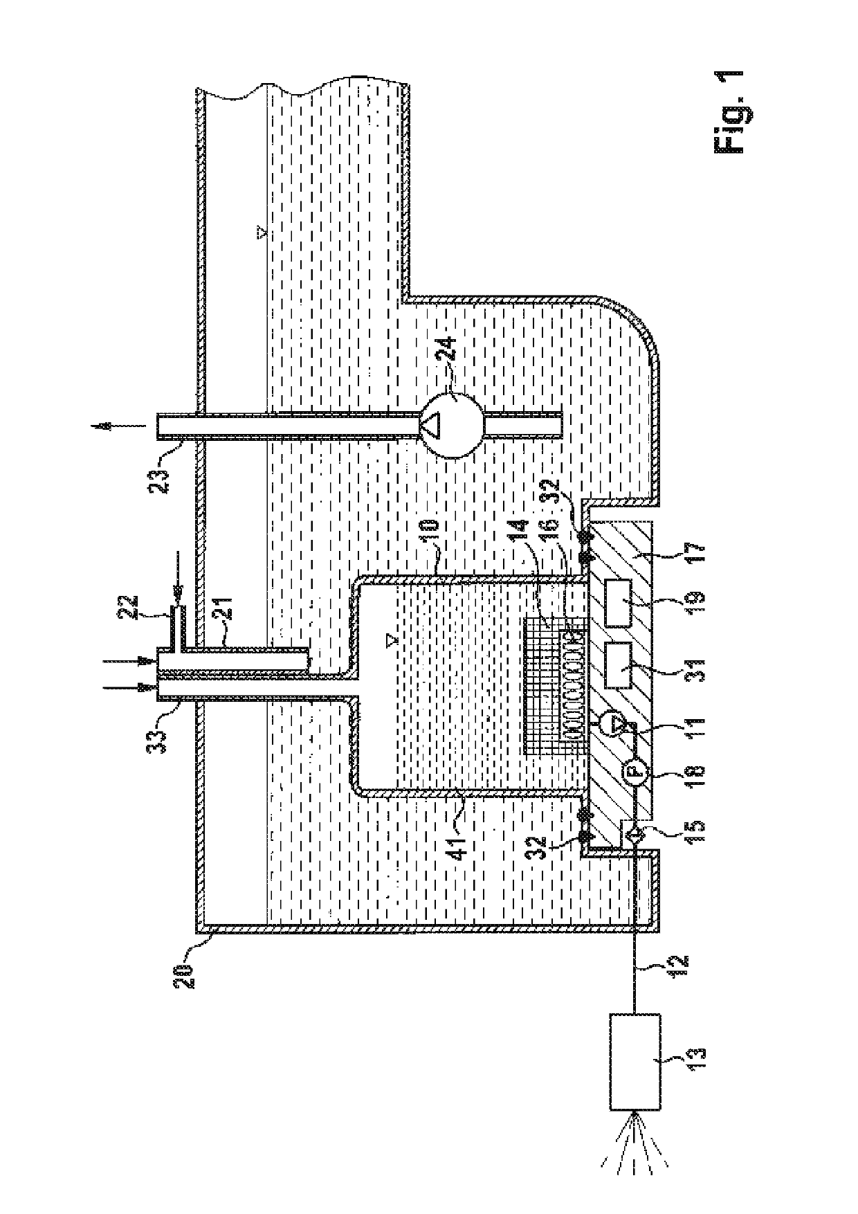
[0015]FIG. 1 illustrates in a schematic way a container assembly according to the invention for a motor vehicle, in which a container 10 for a liquid auxiliary agent, in particular for the reducing agent solution of an SCR catalyst, is integrated into a container 20 for a fuel of the motor vehicle. The auxiliary agent container 10 is arranged in the interior of the fuel container 20. In the sense according to the above description, the container 10 for the auxiliary agent is the second container and the container 20 for the fuel is the first container. The fuel is removed from the container 20 via the removal line 23, which is operated via a pump 24. Thus, the fuel is removed at the top. According to the invention, a removal device for the auxiliary agent is provided at the bottom of the auxiliary agent container 10, wherein the essential element of the removal device is a pump (delivery pump) 11. The delivery pump 11 delivers the auxiliary agent from the container 10 to a metering ...


PUM


Abstract

A container assembly for a motor vehicle comprises a first container (20) for a fuel for the motor vehicle and a second container (10) for a liquid auxiliary agent, in particular for the reducing agent solution of an SCR catalyst. The second container (10) is integrated into the first container (20). A bottom-mounted removal device having at least one pump (11) for removing the auxiliary agent is provided in the second container (10).

Description

BACKGROUND OF THE INVENTION[0001]The present invention relates to a container assembly for a motor vehicle, having a first container for a fuel and a second container for a liquid auxiliary agent. In this assembly, the second container is integrated into the first container.[0002]SCR catalysts (Selective Catalytic Reduction) are known for reducing the content of nitrogen oxides in the exhaust gas from an internal combustion engine. In an SCR catalyst, the nitrogen oxides in the exhaust gas are reduced to elementary nitrogen and water in the presence of a reducing agent. Ammonia (NH3) is used as the reducing agent. To supply ammonia, use is generally made of an aqueous urea solution, which is injected into the exhaust line upstream of the SCR catalyst. To supply the aqueous urea solution, i.e. the reducing agent solution, a tank is provided, this being filled in a workshop in the course of a service, for example. In general, a tank volume of 15 to 30 liters is required. In principle,...

Claims


Application Information

Patent Timeline
Patent Type & Authority Patents(United States)
IPC IPC(8): B60K15/03F01N3/28
CPCF01N3/2896B60K15/03F01N2610/1406F01N2610/02B60K2015/03348B60K2015/03105F01N2610/10F01N3/2066F01N2570/14
Inventor HAEBERER, RAINER
Owner ROBERT BOSCH GMBH
Why Eureka
Try Eureka